Manually Variable Attenuators
50 Ohm Models
- Dual Rotor: step attenuator with two manual knobs
- Single Rotor: step attenuator with one manual knob
- Panel Mounted: 19 inch rack mountable panel models
- Benchtop (enclosure): step attenuator in fully enclosed benchtop enclosure
- Benchtop (L-bracket): step attenuator on benchtop L-bracket
- Pushbutton: step attenuator with pushbutton switches
- Rocker: step attenuator with rocker switches
- Toggle: step attenuator with toggle switches
75 Ohm Models
- Dual Rotor: step attenuator with two manual knobs
- Single Rotor: step attenuator with one manual knob
- Panel Mounted: 19 inch rack mountable panel models
- Benchtop (enclosure): step attenuator in fully enclosed benchtop enclosure
- Benchtop (L-bracket): step attenuator on benchtop L-bracket
- Pushbutton: step attenuator with pushbutton switches
- Toggle: step attenuator with toggle switches
- Display 15 Products per page
-

50 Ohm Dual Rotor Manual Attenuators (17)
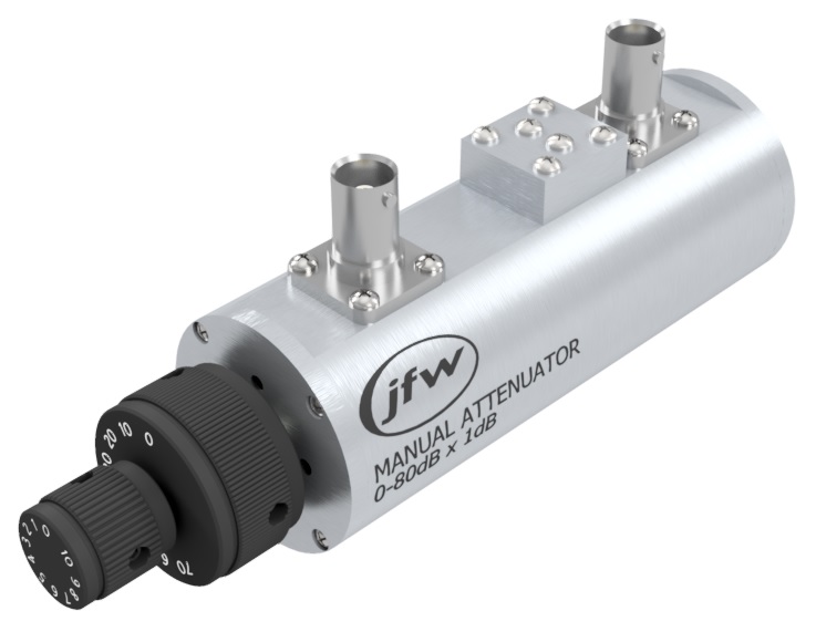
The JFW 50 Ohm dual rotary attenuator has been a staple tool to RF engineers for over 30 years. Our years of proven quality and performance make our manually variable attenuators right for any RF environment. Whether you are using the rotary attenuator on your RF test bench or mounting it to a panel, the JFW dual rotary attenuator makes adjusting attenuation quick and easy. 50 Ohm Dual Rotor Manual Attenuators
Dual Rotor Attenuator
All of these 50 Ohm manual step attenuators are dual rotor type which means that each attenuator has two knobs. For example our 0-110 x 1dB step models have a 10dB step knob and a 1dB step knob. The attenuation setting of the unit is the sum of both knob settings.Panel Mount
All JFW rotary attenuators have threaded mounting holes on the front plate behind the knobs. Both knobs have to be removed in order to mount the attenuator. We recommend setting both knobs to the 0dB position before removing the knobs. Frequently Asked Questions For your specific application, please contact JFW for assistance or use our Inquiry Form. [lt id="65"] -
50 Ohm Panel Mounted Manual Attenuators (13)
JFW's standard 50 Ohm panel mounted rotary attenuator models are listed in the table below. These standard models have 19 inch rack mountable panels. The panel height varies depending on the number of attenuators. We do offer models with empty positions to allow for future expansion of your test setup. JFW can integrate any of our 50 Ohm manually variable attenuators into a panel mounted model. If you have specific requirements (i.e. panel screening, panel color, RF connector configuration) then please contact our engineering team. For model recommendations, please contact JFW or use our Inquiry Form. [lt id="87"] 50 Ohm Panel Mounted Manual Attenuators
 -
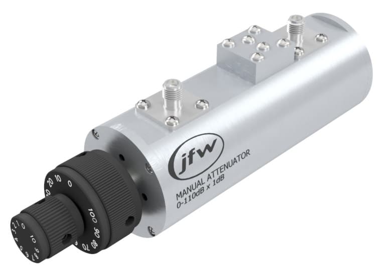
50 Ohm Single Rotor Manual Attenuators (18)
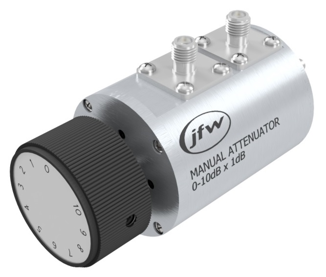
The JFW 50 Ohm single rotary attenuator has been a staple tool to RF engineers for over 30 years. Our years of proven quality and performance make our manually variable attenuators right for any RF environment. Whether you are using the rotary attenuator at your RF test bench or mounting it to a panel, the JFW single rotary attenuator makes adjusting attenuation quick and easy. 50 Ohm Single Rotor Manual Attenuators
Single Rotor Attenuator
All of these 50 Ohm manual step attenuators have a single rotor design which means that each attenuator has only one manual knob for adjusting attenuation.Panel Mount
All JFW rotary attenuators have threaded mounting holes on the front plate behind the knob. The knob has to be removed in order to mount the attenuator. We recommend setting attenuator to the 0dB position before removing the knob. Frequently Asked Questions For your specific attenuation application, please contact JFW or use our Inquiry Form. [lt id="64"] -
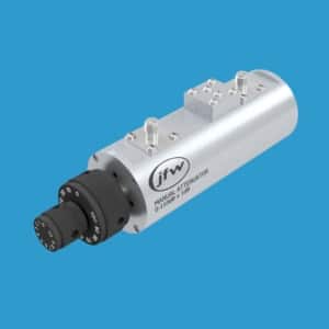
75 Ohm Dual Rotor Manual Attenuators (9)
The JFW 75 Ohm dual rotary attenuator has been a staple tool to RF engineers for over 30 years. Our years of proven quality and performance make our manually variable attenuators right for any RF environment. Whether you are using the rotary attenuator on your RF test bench or mounting it to a panel, the JFW dual rotary attenuator makes adjusting attenuation quick and easy. 75 Ohm Dual Rotor Manual Attenuators
Dual Rotor Attenuator
All of these 75 Ohm manual step attenuators are dual rotor type which means that each attenuator has two knobs. For example our 0-110 x 1dB step models have a 10dB step knob and a 1dB step knob. The attenuation setting of the unit is the sum of both knob settings.Panel Mount
All JFW rotary attenuators have threaded mounting holes on the front plate behind the knobs. Both knobs have to be removed in order to mount the attenuator. We recommend setting both knobs to the 0dB position before removing the knobs. Frequently Asked Questions For your specific application, please contact JFW for assistance or use our Inquiry Form. [lt id="54"] -
75 Ohm Panel Mounted Manual Attenuators (6)
JFW’s standard 75 Ohm panel mounted rotary attenuator models are listed in the table below. These standard models have 19 inch rack mountable panels. The panel height varies depending on the number of attenuators. We do offer models with empty positions to allow for future expansion of your test setup. JFW can integrate any of our 75 Ohm manually variable attenuators into a panel mounted model. If you have specific requirements (i.e. panel screening, panel color, RF connector configuration) then please contact our engineering team. For model recommendations, please contact JFW or use our Inquiry Form. [lt id="86"] 75 Ohm Panel Mounted Manual Attenuators
 -
75 Ohm Single Rotor Manual Attenuators (8)
The JFW 75 Ohm single rotary attenuator has been a staple tool to RF engineers for over 30 years. Our years of proven quality and performance make our manually variable attenuators right for any RF environment. Whether you are using the rotary attenuator at your RF test bench or mounting it to a panel, the JFW single rotary attenuator makes adjusting attenuation quick and easy. 75 Ohm Single Rotor Manual Attenuators
Single Rotor Attenuator
All of these 75 Ohm manual step attenuators have a single rotor design which means that each attenuator has only one manual knob for adjusting attenuation. All manual knobs are screened with the attenuation steps for each model.Panel Mount
All JFW rotary attenuators have threaded mounting holes on the front plate behind the knob. The knob has to be removed in order to mount the attenuator. We recommend setting attenuator to the 0dB position before removing the knob. Frequently Asked Questions For your specific attenuation application, please contact JFW or use our Inquiry Form. [lt id="31"] -
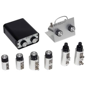
Benchtop Manual Attenuators (Enclosure) (15)
Benchtop manual attenuators are a staple RF test bench piece of equipment. Simple to control and requires no AC power to operate. These online models have the RF connectors on the rear panel and the manual knobs on the front panel. For your specific application, please contact JFW for assistance or use our Inquiry Form. Benchtop Manual Attenuators (Enclosure)
Step Attenuator Design
The benchtop attenuator assemblies use step attenuators internally. The step attenuators are connected in series with each other. The attenuation setting of the assembly is the sum of the attenuation indicated by both knobs.50 Ohm Models
[lt id="79"]75 Ohm Models
[lt id="130"] If you can't find an online model to meet your requirements, please contact JFW. We can integrate any of our manually variable attenuators into a benchtop enclosure per your specific configuration. JFW does not charge NRE's to design models. We pride ourselves in the ability to offer custom models with the same pricing and delivery as our standard models. -
Benchtop Manual Attenuators (L-Bracket) (8)
JFW's benchtop rotary attenuator models with L-brackets are listed in the table below. The RF connectors are accessible on the rear side of the L-bracket and the manual knobs are located on the front of the L-bracket Benchtop Manual Attenuators (L-Bracket)
Step Attenuator Design
The benchtop attenuator assemblies use our standard manual step attenuators. The step attenuators are connected in series with each other. The attenuation setting of the assembly is the sum of the attenuation indicated by both knobs. Frequently Asked Questions For your specific application, please contact JFW for assistance or use our Inquiry Form. [lt id="78"] -
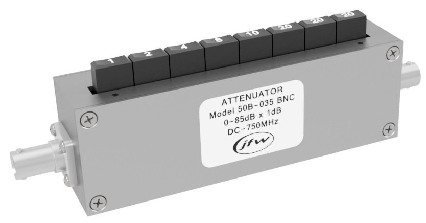
Pushbutton Attenuators (10)
The JFW pushbutton attenuator has been a staple tool to RF engineers for over 30 years. Whether mounted to a panel or used at a RF test bench, the JFW pushbutton attenuator makes adjusting attenuation quick and easy. Pushbutton Attenuators
Step Attenuator Design
Each pushbutton controls an individual attenuation step. In order to achieve combinational dB settings you must activate multiple attenuation steps simultaneously.Panel Mount Options
Most JFW pushbutton attenuators have threaded mounting holes on the same side as pushbuttons. These mounting holes are denoted on the outline drawings. For your specific application, please contact JFW or use our Inquiry Form. [lt id="55"] -
Rocker Attenuators (2)
The JFW rocker attenuator makes adjusting attenuation quick and easy. Use the rocker switches on the top plate to manually set your desired attenuation. These are passive attenuation devices that require no DC Voltage for operation. Each rocker switch controls an individual attenuation step. Activate multiple rocker switches simultaneously to set combinational dB settings. [lt id="24"] Rocker Attenuators
 -
Toggle Attenuators (4)
Whether you are using a toggle attenuator at your RF test bench or mounting it to a panel, the JFW toggle attenuator makes adjusting attenuation quick and easy. Toggle Attenuators
Step Attenuator Design
Each toggle controls an individual attenuation step. In order to achieve combinational dB settings you must activate multiple attenuation steps simultaneously.Panel Mount Options
Most JFW toggle attenuators have threaded mounting holes on the same side as toggle switches. These mounting holes are denoted on the outline drawings. For your specific RF testing application, please contact JFW for assistance. [lt id="25"]
 50 Ohm Dual Rotor Manual Attenuators
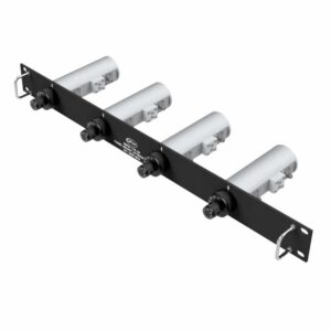
 50 Ohm Panel Mounted Manual Attenuators
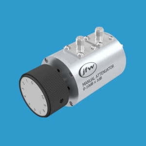
 50 Ohm Single Rotor Manual Attenuators
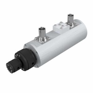
 75 Ohm Dual Rotor Manual Attenuators
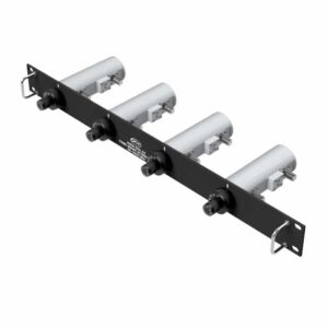
 75 Ohm Panel Mounted Manual Attenuators
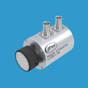
 75 Ohm Single Rotor Manual Attenuators
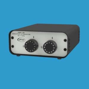
 Benchtop Manual Attenuators (Enclosure)
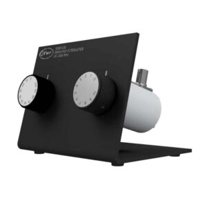
 Benchtop Manual Attenuators (L-Bracket)
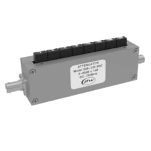
 Pushbutton Attenuators
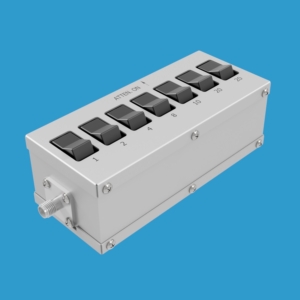
 Rocker Attenuators
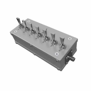
 Toggle Attenuators