Handover Test Systems for Cellular Testing
Family of handover test systems designed for handset-to-network handover testing. Internal step attenuators allow the RF signal between the network access points and the handsets to be dynamically faded up/down. The Ethernet/Serial models run our latest generation 3.x.x firmware that features easy to use ASCII formatted commands.
- Full fan-out models provide the greatest testing flexibility with individually controlled step attenuator on every RF path thru the matrix.
- Limited fan-out models use a common highway configuration which reduces the number of internal paths and the number of attenuators.
- Manual handover models use manually controlled attenuators for simple benchtop testing.
- Display 15 Products per page
-

Full Fan-out Handover Test Systems for Cellular Testing (21)
Whether you are fading multiple base station signals to a handset or testing multiple communication standards with wireless devices, JFW has a handover test system to help automate your RF testing. JFW's full fan-out handover test systems are a type of matrix switch that is constructed with power divider/combiners on both halves of the matrix with programmable attenuators in between. There is an individually controlled programmable attenuator on every RF path through the matrix. This type of construction allows every input signal to be available simultaneously to every output port at differently attenuated signal levels. For assistance choosing a model, please contact JFW or use our Inquiry Form. [lt id="94"] Full Fan-out Handover Test Systems for Cellular Testing
Full Fan-out Handover Test System Example
The below block diagrams show examples of a full fan-out 4 X 2 handover test system. Each path through the test system has its own individually controlled programmable attenuator. This configuration allows for each input signal to be simultaneously available to each output port at differently attenuated signal levels. The isolation between output ports is determined by summing the isolation of the input power divider/combiner (typically 20dB for reactive type dividers) with the attenuation setting of the programmable attenuators connected to the same input port. That makes it important to keep programmable attenuators on unused paths at their maximum attenuation setting in order to maximize system isolation.Block Diagram #1
This block diagram illustrates the construction of the full fan-out 4 x 2 handover test system. It shows all of the connectivity between the input ports and the output ports. This design allows the RF signal on input #1 to be simultaneously available to both outputs at different signal levels.
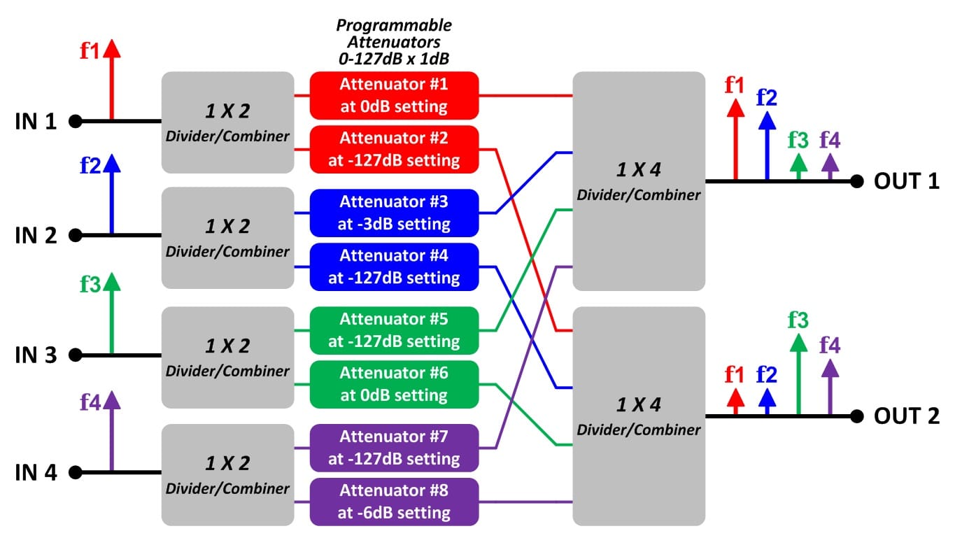
Block Diagram #2
This block diagram shows one possible setting of a full fan-out 4 x 2 handover test system. There are four input signals (red, blue, green, purple). The 1 x 2 power divider/combiners split up the input signals to both output ports. The 1 x 4 divider/combiners sum up all of the input signals for each output port. Attenuator #1 sets f1 at 0dB of attenuation for Output #1. Attenuator #2 sets f2 at 127dB of attenuation for Output #2. The RF signal on input port #1 is simultaneously available to both output ports at different signal levels.
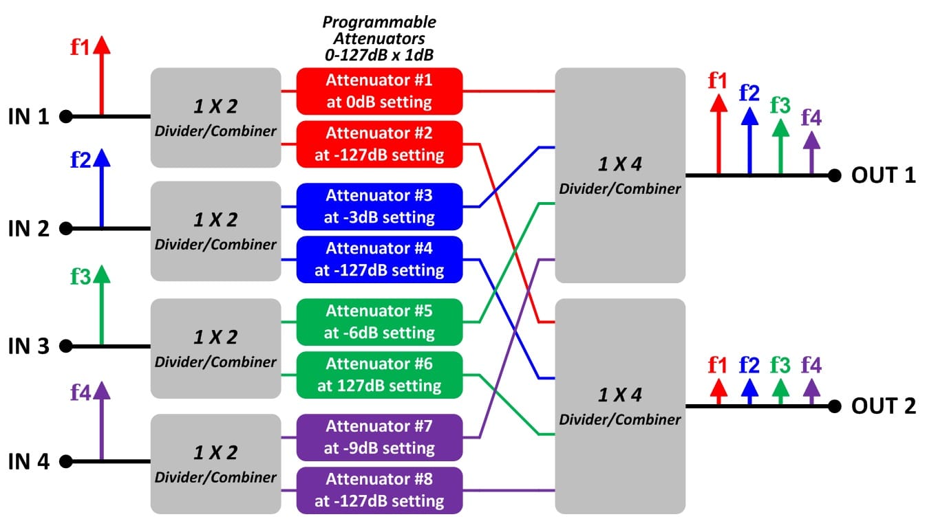
Block Diagram #3
This block diagram shows another possible setting of a full fan-out 4 x 2 handover test system. The 1 x 2 power divider/combiners split up the input signals to both output ports. The 1 x 4 divider/combiners sum up all of the input signals for each output port. For this example the user on output port #2 has turned off all of the input signals. The user does this by setting all of the programmable attenuators connected to output #2 to their maximum attenuation setting (i.e. 127dB). The programmable attenuators connected to output port #1 are set to various attenuation settings (i.e. 0dB, 3dB, 6dB, 9dB).
Custom Models
JFW does not charge NRE's for custom test system models. Please email us your specific requirement. We will respond with a ROM (rough order of magnitude) quote in 1-2 days.Remote Commands
The handover test system models are available with Ethernet/Serial remote control. Our current generation of Ethernet/Serial firmware is called 3.x.x firmware. It features easy to use ASCII formatted remote commands. Use our Ethernet Test Box to demo the 3.x.x firmware.Test Software
JFW provides a GUI test program with all Ethernet and RS-232 controlled test systems. The test software for handover test systems has all of the remote commands built in for easy testing. Jump to our sample test programs to see example programs. -
Limited Fan-out Handover Test Systems for Cellular Testing (17)
Whether you are fading multiple base station signals to a handset or testing multiple communication standards with wireless devices, JFW has a handover test system to help automate your RF testing. JFW's limited fan-out configuration (LC) handover test systems are scaled down versions of our full fan-out handover test systems. These limited fan-out models have individually controlled programmable attenuators on the input ports. All of the input signals are summed together and then split up to all of the output ports. This type of construction allows an input signal to be available to all output ports at the same attenuation level. Because the limited configuration models use fewer RF components than the full fan-out models, the cost of the limited configuration models is lower. Example block diagrams are located below the model selection table. For your specific application, please contact JFW for assistance or use our Inquiry Form. [lt id="80"] Limited Fan-out Handover Test Systems for Cellular Testing
LC Handover Test System Example
The below block diagrams show examples of a 4 X 2 limited fan-out configuration (LC) handover test system. Each input port has its own individually controlled programmable attenuator. The input signals are summed together by the 1X4 divider/combiner and then split to both output ports by the 1X2 divider/combiner. An input signal is simultaneously available to both output port at the same attenuated level. The isolation between the two output ports is determined by the isolation of the 1X2 divider/combiner. Reactive power divider/combiners typically have 20dB of port to port isolation. The isolation between input ports is determined by the isolation of the 1X4 divider/combiner. Keep programmable attenuators on unused paths at their maximum attenuation setting in order to maximize input to input isolation.Block Diagram #1
This block diagram illustrates the construction of the 4 X 2 limited fan-out configuration (LC) handover test system. It shows all of the connectivity between the input ports and the output ports. This design allows the RF signal on input #1 to be simultaneously available to both outputs at the same attenuation level.
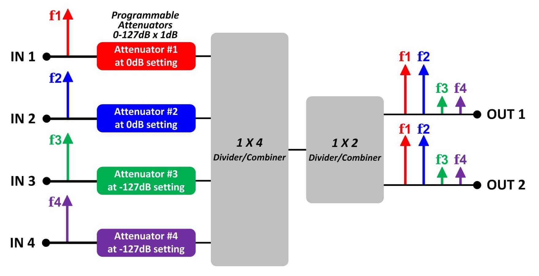
Block Diagram #2
This block diagram shows one possible setting of the 4 X 2 limited fan-out configuration (LC) handover test system. There are four input signals (red, blue, green, purple). The 1X4 divider/combiner sums up all of the input signals. The 1X2 divider/combiner splits the signals up to both output ports. Attenuators #1 and #2 attenuate their input signals at 0dB. Attenuators #3 and #4 attenuate their input signals at 0dB. The output signal for output #1 is identical to the output signal on output #2.
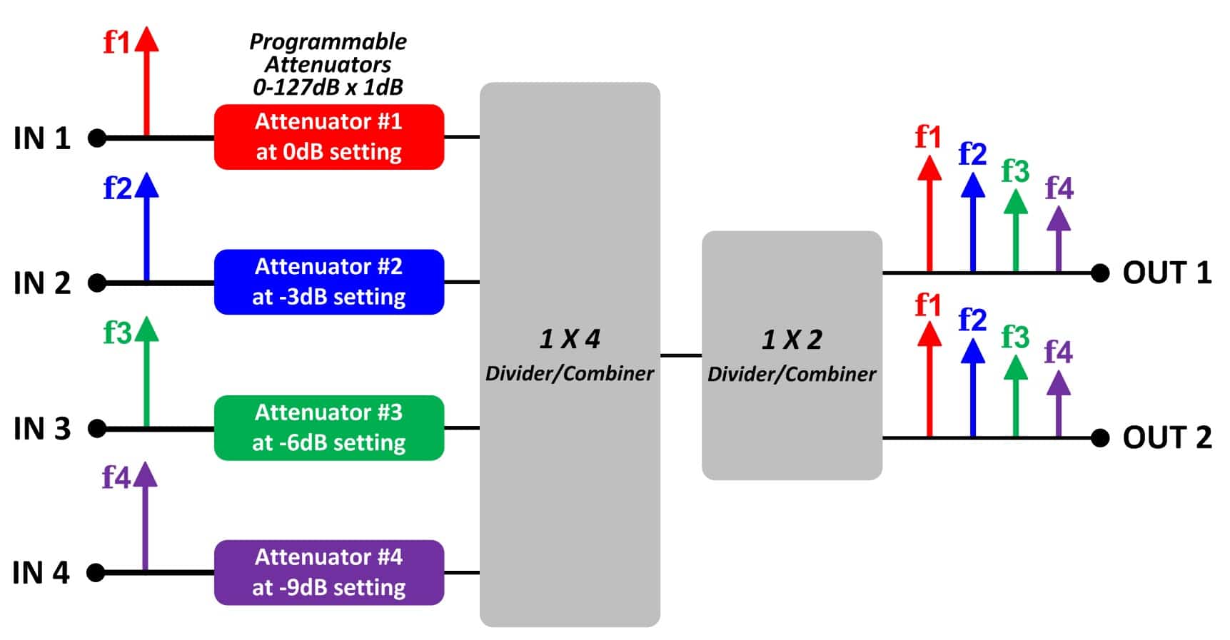
Block Diagram #3
This block diagram shows another possible setting of the 4 X 2 limited fan-out configuration (LC) handover test system. There are four input signals (red, blue, green, purple). The 1X4 divider/combiner sums up all of the input signals. The 1X2 divider/combiner splits the signals up to both output ports. Each programmable attenuator is set to a different attenuation level (0db, 3dB, 6dB, 9dB). The output signal for output #1 is identical to the output signal on output #2.
Custom Models
JFW does not charge NRE's for custom test system models. Please email us your specific requirement. We will respond with a ROM (rough order of magnitude) quote in 1-2 days.Remote Commands
The handover test system models are available with Ethernet/Serial remote control. Our current generation of Ethernet/Serial firmware is called 3.x.x firmware. It features easy to use ASCII formatted remote commands. Use our Ethernet Test Box to demo the 3.x.x firmware.Test Software
JFW provides a GUI test program with all Ethernet and RS-232 controlled test systems. The test software for handover test systems has all of the remote commands built in for easy testing. Jump to our sample test programs to see example programs. -
Manual Handover Systems (5)
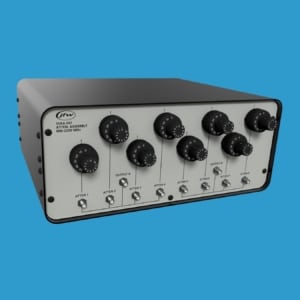
JFW's manual handover test systems provide a simple solution for RF testing wireless devices by combining our manual rotary attenuators and RF power divider/combiners into a convenient benchtop enclosure. All of the internal RF components are passive so no power supply is needed to operate the test systems. Simply turn the knobs to adjust each attenuator setting. Adjust a single manual attenuator to perform a signal fade test. Use two manual attenuators simultaneously to perform a manual handover test. [lt id="81"] Manual Handover Systems
Custom Models Available
For your specific testing configuration, please use our Inquiry Form or email your block diagram to our engineering team.Manual 4 x 1 LC Handover System
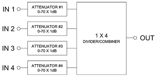
The below block diagram is an example of a manual 4 x 1 LC handover test system. Four different communication standards (i.e. Wi-Fi, WiMAX, LTE) can be connected to the four input ports. Each communication standard can be attenuated to different levels. The output port containing all four communication standards is then connected to the handheld device.
Manual 3 x 4 LC Handover System
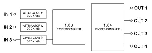
The below block diagram is an example of a manual 3 x 4 LC handover test system. Three different communication standards (i.e. Wi-Fi, WiMAX, LTE) can be connected to the input ports. Each communication standard can be attenuated to different levels. The three communication types are combined together and then split into four signals. This configuration allows testing of four handheld devices at the same time.
 Full Fan-out Handover Test Systems for Cellular Testing
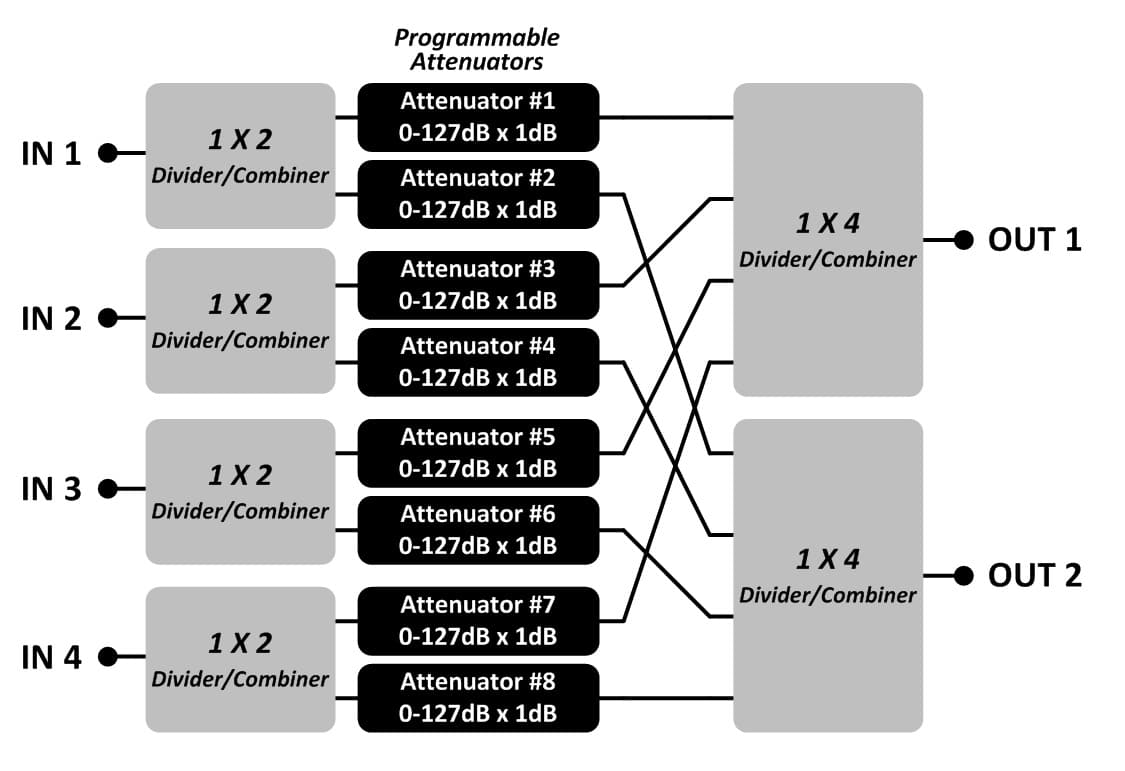
 Limited Fan-out Handover Test Systems for Cellular Testing
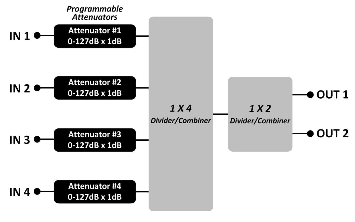
 Manual Handover Systems