Introduction to JFW’s USB Attenuator Test Software
Why use a USB Attenuator?
In RF test labs, programmable attenuators and RF switches are a basic building block of performance testing. Programmable attenuators are used in fading, handover, and rate vs range testing. Among other things, RF switches are used in signal routing, component bypassing and switched filter banks. To fill this need, JFW offers an expansive selection of Programmable Attenuator Assemblies and RF Switch Assemblies in 19″ rack or benchtop enclosures. These boxes typically include Ethernet and RS-232 control. While appropriate for medium to large testing environments, a USB Attenuator or USB RF Switch is often a better solution for smaller test setups. Lower cost and smaller size of the USB device are especially relevant.
JFW has been designing and building programmable attenuators for nearly 40 years, and introduced our first USB attenuator in 2014. Since then, we have expanded our selection of USB attenuators and USB RF switches. We include our USB test software at no extra charge with the purchase of any of these devices. This is a Windows based utility that makes it simple to send commands to the devices. In addition, you can build more complex scripts for automated testing. This software can be used for any USB attenuator or USB RF switch that we manufacture.
The images below show several screenshots of the USB attenuator test software: (1) When initially launched. (2) An Attenuator Control Box appears in the GUI window as soon as a device is connected. (3) As additional units are connected (either directly or through a USB hub) a new box spawns in the upper section of the GUI.
[envira-gallery id=”37079″]
Digging into the Attenuator Control Box
Each Attenuator Control Box has several elements:
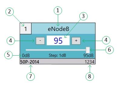
1. The name of the attenuator. Change the name by double-clicking on it and entering a new name. The device saves the new name in memory, and it persists through power cycles.
2. The attenuator number, which is used with more complex commands such as fade and handover.
3. The current attenuator setting, measured in dB. To change the attenuation to a specific value, double-click and enter a new value.
4. The minus and plus boxes will decrement or increment the attenuator setting by 1 step.
5. This line of information shows the minimum attenuation setting, the step size, and the maximum attenuation setting.
6. The slider bar allows large changes to the attenuation to be made quickly.
7. The JFW model number.
8. The JFW serial number is shown (will match what is printed on the unit).
That covers the basic operation of the USB test software. Part 2 will cover advanced commands and scripting. More information can be found in our USB Test Software Manual.