Testing with Mismatch Terminations
This application note examines the advantages of using VSWR mismatched loads when testing RF amplifiers.
The value of testing with mismatch terminations
By: Murray Slovick
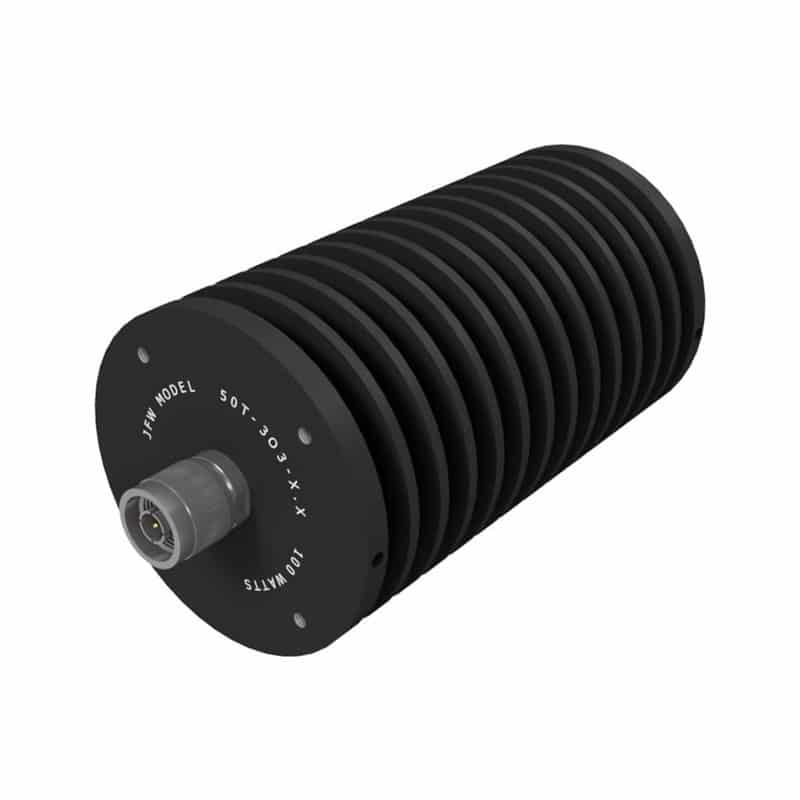
Figure 1: A 100 W high power termination and mismatch (model 50T-303-XXX). Source: JFW Industries
Mismatch loads can be used to test amplifiers and help characterize their performance under conditions that might occur in the field. To do so, a mismatch load (or mismatch termination) is used to present a specified VSWR, rather than the usual 1:1 perfect 50 ohm load.
There are many situations in which it becomes necessary to match the impedance of a load to that of the source so as to maximize power transfer. Having a mismatch between a source (an amplifier) and a load reduces the delivered power and efficiency of the system; when a transmission line is terminated with impedance that is not equal to the characteristic impedance of the line, not all of the incident power is absorbed by the termination. Some of the power is reflected back to the source.
While terminations are employed to prevent such signal reflections, mismatch terminations can be useful in providing a quick and easy method for calibrating equipment or checking the performance of an amplifier. The value of testing with mismatch terminations is significant because high-efficiency amplifiers can be characterized by their ability to drive mismatched loads.
The principal figure of merit concerning what happens with having an impedance mismatch is voltage standing wave ratio (VSWR). VSWR is determined by sending signals at various frequencies through the cable to the 50 ohm load under test and observing what signals are reflected. The amount of energy reflected depends on the level of the mismatch, so VSWR will be a value above 1. As VSWR increases, so does the amount of lost power.
For example, at a 6:1 VSWR, 50% of power is lost as wasted energy. As such, it may require a larger amplifier to compensate, resulting in higher cost. Having a high VSWR can also stress all the internal components. This stress can manifest itself as heat dissipation or higher voltages, possibly even approaching voltage breakdown limits.
The impedance mismatch VSWR is indicated by the magnitude of the reflection coefficient written as an “uppercase Gamma” (Γ), which can be calculated from the values of the load impedance and the transmission line characteristic impedance. VSWR is a complex number (it includes an angle) and is defined as VSWR = (1 + Γ )/(1 – Γ ). The bigger the mismatch of impedance, the larger the VSWR.
Similarly, return loss can be calculated from the reflection coefficient with the equation:
Return loss = -20*Log(Γ)
As previously noted, mismatches can be used to create reflections for testing purposes. Companies like JFW Industries can make a mismatch load (or mismatch termination) that can be used to test amplifiers and help characterize their performance under conditions that might occur in the field. These present a specified VSWR rather than the perfect 1:1 50 ohm load.
JFW Industries’ mismatched loads have model numbers that end with -XXX. Model 50T-303-XXX (pictured above), for example, can be ordered as a 50 ohm termination or as a mismatch load. The heatsink is round with mounting holes on both ends. This model is rated at 100 W RF input power. The mismatch load VSWR values can be specified up to 10.0:1.
These low-power mismatch terminations are a handy addition to the equipment in any test laboratory.
