Handover Test Systems Reach 8 GHz For Wi-Fi 6E and 5G Applications
 In order to remain competitive and offer the latest in high-speed services, cellular hardware and Internet-of-Things (IoT) device manufacturers and system operators are moving to higher frequencies now available with Wi-Fi 6E (5.925 GHz to 7.125 GHz) and mid-band 5G (sub-6 GHz). Moreover, these latest devices now operate in a wider variety of network topologies and modes than legacy systems, including mesh and heterogeneous cellular systems. This means that developing hardware/software and testing the latest wireless systems/devices require specifically designed test systems that have the frequency range, flexibility, and port count necessary to emulate a complex environment with a greater mix of device types.
Breakdown of Handover Test Systems
Handover test systems are generally composed of divider/combiners, variable attenuators, and sometimes integrated switches. The idea is that the ports of DUTs (Devices Under Test) can be routed to multiple simulated transceivers, or actual cellular radio hardware, used to replicate the behavior of a fielded wireless network. Fading, multipath fading, and forced-handover testing are key uses of handover test systems. These units are critical in developing the hardware, software, and protocols for handling handovers and other complex network scenarios.
In legacy cellular or Wi-Fi fading or handover testing, there are typically only a couple of DUTs, often user equipment and two cell tower base stations. However, evolving 5G and Wi-Fi 6e user devices and cellular infrastructure now have much more complex multi-band transceivers and operate in new frequency bands to 6 GHz for 5G and nearly 8 GHz for Wi-Fi 6e. The latest 5G and Wi-Fi standards also enable mesh networking and/or peer-to-peer (P2P) modes, where multiple devices can operate in a peer-to-peer mode without central infrastructure handling the communications. There are also an increasing number of cell installations and distributed-antenna-systems (DAS) that support multiple cellular bands and Wi-Fi, or at least coexist in close proximity with them. With at least coexistence and with a possible future convergence of Wi-Fi and cellular, it is also increasingly valuable to have test systems on hand that are suitable for both wireless standards.
This is why in many modern 5G and Wi-Fi 6e applications, it is necessary to have some version of a handover test system capable of full fan-out connectivity. A full fan-out test system enables each input port to be available to any/all output ports simultaneously with an individually controlled
programmable attenuator in each RF path. With full fan-out, a test system can be used to emulate much more complex and nuanced scenarios that can be crucial in developing 5G and Wi-Fi 6e hardware and software.
Specifying Handover Test System Requirements
The latest handover test systems for evaluating 5G sub-6 GHz and Wi-Fi 6e devices and infrastructure need to accommodate frequencies from around 1 GHz to nearly 8 GHz. This frequency range also covers essentially all Internet-of-Things (IoT) devices with operating frequencies above 1 GHz. It is
important that the components in the handover test system all have relatively flat insertion loss across the frequency range of the service of interest to prevent any artifacts of the test system impacting the system hardware/software design.
The fading features of a handover test system are predominately dictated by the variable attenuators used in the system. The attenuation step resolution, often given in dB, determines how refined a fading profile can be. The maximum attenuation value and the overall system insertion loss dictates the maximum and minimum attenuation. This is due to some insertion loss involved in each connection, switch, and power divider/combiner.
Depending on the desired agility of the wireless network, switching speeds may be critical. For some 5G applications with extremely high mobility user equipment, such as automobiles, speeds in the microseconds may be essential. This is the time it takes for the switch to transition and settle, which also depends on the power of the signal, which will insert some limitations in the maximum power handling capability during hot switching. In many cases, the switch and power divider/combiner isolation can also be a key performance metric depending on the desired test system isolation.
Input and output power handling must also be specified for given systems, and any of the handover test system components could be a limiting factor in the overall system capability. It is important to note that the input and output power handling for programmable attenuators will be different and to specify a system accordingly.
What If My Application Requires A Custom Configuration?
Often with IoT, 5G, and Wi-Fi handover test systems, there isn’t a one-size-fits-all solution. In many cases, specific system requirements may need higher performance features, where other features are less critical. An example of this is a particular system needing higher levels of attenuation, but the step size may be lower resolution. Having customizable configuration options with a handover test system can be an enabling factor in the development of wireless network technology.
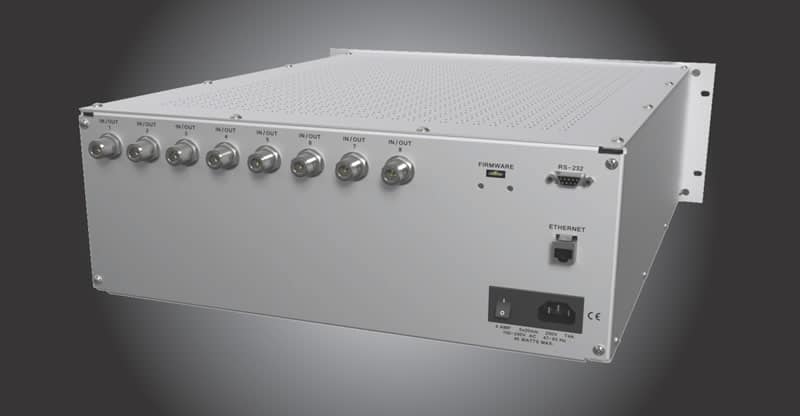
An Example of a 1000 to 8000 MHz 4×4 Full Fan-out Handover Test System
To accommodate the needs of 5G and Wi-Fi 6e wireless network hardware and system developers, JFW has recently released a 1 GHz to 8 GHz 4×4 Full Fan-out Handover Test system. This system is specifically designed to meet the performance requirements of the latest 5G sub-6 GHz and Wi-Fi 6e standards in a compact and standard 19 in rack mount unit. Once integrated into a lab, the handover system can be used to connect up to four mobile devices to as many as four network sources. Then, by manipulating the programmable attenuators between each point of connectivity, users can emulate real-world scenarios where radios are forced to choose between sources of varying RF signal strength. This unit can be controlled manually via the integrated front-panel control interface, with Ethernet, or using RS-232 serial communication. This unit allows users to write and execute complicated, scripted test routines to replicate specific RF environments encountered in the field and it makes for easy integration into API level test management software. Additional built-in functions like JFW’s Fade command simplify programming even more (Fade command automatically raises and/or lowers attenuation in regular intervals). The maximum attenuation per line is 95 dB with programmable attenuator step size of 1 dB. The connector types for this unit can be configured as either N-type or SMA female (50 Ohm).
Resources
1. https://www.jfwindustries.com/new-products/wi-fi-6e-passive-components-and-rf-test-systems/
2. https://www.jfwindustries.com/product/4-x-4-handover-test-system-1-8-ghz-50pa-1248/

