What is the difference between reactive and resistive power dividers?
Understanding the difference between reactive and resistive power dividers will help you create the best functionality for your RF testing setup. Their functionality is similar but yet different.
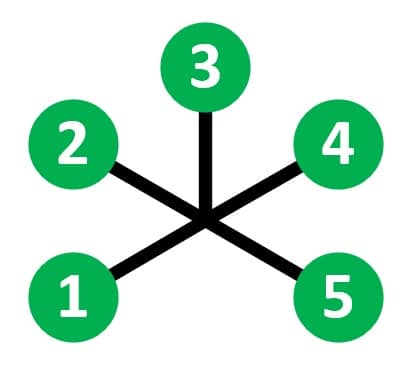
Resistive Power Dividers
Their construction is a star configuration. All ports are symmetrical. There is no common port with resistive type design. The star configurations functions as a RF hub. A signal into port 1 will be divided up equally to ports 2, 3, 4, 5. This type of functionality makes resistive type power divider/combiners ideal for connecting multiple radios together. All radios connected to the resistive divider/combiner have equal loss from radio-to-radio.
Resistive Characteristics:
-
- Symmetrical layout
- Star configuration (aka RF hub)
- All paths have equal loss
- No isolation paths
- Frequency ranges: DC-1GHz, DC-4GHz, DC-6 GHz
Resistive Use Cases:
-
- Connect multiple wireless devices in a star configuration
- Connect radios together with RF hub functionality
- Available resistive models: lower power or high power
Reactive Power Dividers
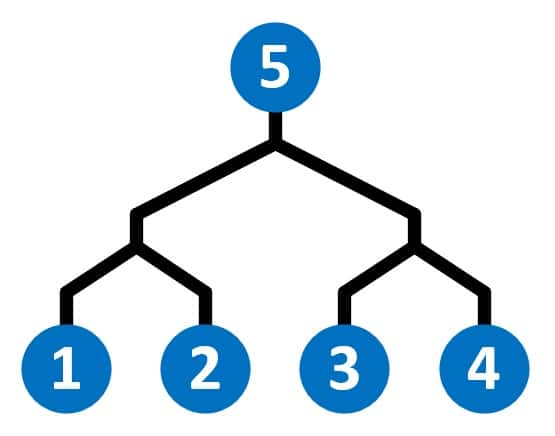
Their construction is non-symmetrical. A signal into the divider port (port 5) is divided up to all of the combiner ports (ports 1, 2, 3, 4). Signals into ports 1, 2, 3, 4 will all be combined together at port 5. The loss from divider port to a combiner port is equal for all paths. However, the loss between combiner ports is typically >20dB regardless of configuration (i.e. 1X2, 1X4, 1X8). The loss between combiner ports is referred to as isolation. The fact that the combiner ports are isolated from each other at >20dB typical makes reactive divider/combiners useful to fan-out a signal to multiple devices or fan-in signals from multiple devices.
Reactive Characteristics:
-
- Non-symmetrical layout
- Common port design
- Fan-in or fan-out functionality
- Isolation between combiner ports
Reactive Use Cases:
-
- Fan-out a RF signal with minimum loss
- Fan-in multiple RF signals with minimum loss
- Connect test equipment to multiple DUTs with minimum loss
- Frequency ranges: 30-3000MHz, 0.5-6GHz, 0.5-18GHz, 6-40GHz
- Available reactive models: lower power or high power
Through Path Loss Examples
There is a significant difference in through path loss between resistive and reactive type power divider/combiners. A resistive model has twice the through path loss compared to the corresponding reactive model. Below is a chart showing the through path loss differences for common configurations. The losses shown are the calculated theoretical split losses for each configuration.
Split Loss for 2-Way (1X2)
-
- -6.02dB resistive type
- -3dB reactive type
Split Loss for 4-Way (1X4)
-
- -12.04dB resistive type
- -6dB reactive type
Split Loss for 8-Way (1X8)
-
- -18.06dB resistive type
- -9dB reactive type
Split Loss for 16-Way (1X16)
-
- -24.08dB resistive type
- -12dB reactive type