What is the use of a fixed attenuator?
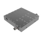
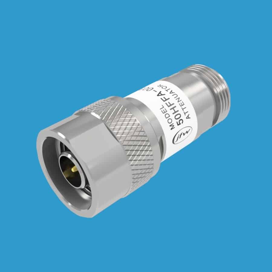
A fixed attenuator has two main uses: decrease signal power level, improve poor VSWR. A fixed attenuator is a passive device with internal resistors whose resistive values are calculated base on the impedance (50 Ohm or 75 Ohm) and the desired attenuation value. The attenuation value is expressed in terms of decibel (dB). When the signal is reduced (i.e. attenuated) it is converted into heat. The greater the dB value, the hotter the attenuator will run because it is converting more of the signal into heat. If you are using the fixed attenuator inside of a chassis with poor airflow, consider choosing an attenuator model with a larger heatsink so that is will run cooler or add a fan for forced air. We use fixed attenuators inside of our own test systems, please email our engineering department if you would like any recommendations.
Downloadable PDF selection charts:
-
- dB selection chart for signal reduction
- VSWR reduction chart
Decreasing signal level with a Fixed Attenuator
A fixed attenuator will decrease the RF signal level by a specific dB (decibel) value. The dB value can be calculated using input power and desired output power with the below equation. Or you can use our dB selection chart which lists output power levels for many standard dB values.
dB = 10 x log(output power/input power)
21% reduction in power: 10 x log(79W/100W) = -1.02 dB
37% reduction in power: 10 x log(63W/100W) = -2.01 dB
50% reduction in power: 10 x log(50W/100W) = -3.01 dB
75% reduction in power: 10 x log(25W/100W) = -6.02 dB
90% reduction in power: 10 x log(10W/100W) = -10 dB
99% reduction in power: 10 x log(1W/100W) = -20 dB
99.9% reduction in power: 10 x log(0.1W/100W) = -30 dB
99.99% reduction in power: 10 x log(0.01W/100W) = -40 dB
Improving Poor VSWR with a Fixed Attenuator
A fixed attenuator can also be used to improve VSWR. If you are building a RF sub-system and put several RF components in series, the resulting port VSWR will be a higher value because the component VSWRs add together. A fixed attenuator can be added right at the port to improve the port VSWR. Our VSWR reduction chart lists reduction levels for several standard dB values. Here are some example VSWR improvements using different dB values:
3.0:1 → reduced by 1dB attenuator → 2.318:1
3.0:1 → reduced by 2dB attenuator → 1.922:1
3.0:1 → reduced by 3dB attenuator → 1.669:1
3.0:1 → reduced by 4dB attenuator → 1.497:1
3.0:1 → reduced by 5dB attenuator → 1.376:1
3.0:1 → reduced by 6dB attenuator → 1.287:1
3.0:1 → reduced by 7dB attenuator → 1.222:1
3.0:1 → reduced by 8dB attenuator → 1.172:1
3.0:1 → reduced by 9dB attenuator → 1.134:1