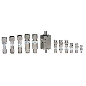
Test Accessories
- Bias Taps: Inject DC Voltage onto a coaxial cable
- Couplers: Monitor signal levels with resistive or directional coupler
- DC Blocks: Block DC Voltage on a coaxial cable
- DC Cables: Mates to our attenuator and RF switch models
- Feedthru Terminations: Impedance matching for oscilloscopes
- Impedance Matching Pads: Resistive impedance matching
- Impedance Matching Transformers: Reactive impedance matching
- RF Adapters: 50 Ohm and 75 Ohm coaxial adapters
- RF Cables: 50 Ohm and 75 Ohm coaxial cable assemblies
- RF Detectors: Convert a RF signal into a DC signal
- RF Fuse Holders: Insert a fuse to a coaxial cable run
- Sort by Average rating
- Display 45 Products per page
-
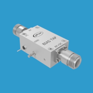
Bias Taps (13)
Bias taps (aka Bias tees) have been a staple product in JFW's line of quality RF test accessories for over 25 years. They can be used to inject a DC Voltage onto a RF signal.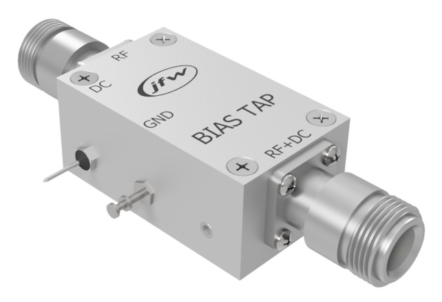 Bias Taps
- 50 Ohm and 75 Ohm Bias Taps
- Low insertion loss
- DC current handling up to 5 Amps
- DC Voltage capacity up to 200 Volts
- Any RF connector combination (BNC, SMA, N, TNC, 7/16)
-
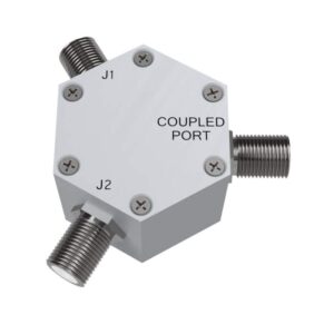
Couplers (12)
Couplers
Couplers can be used to monitor a RF signal while adding very little insertion loss to the RF path. JFW offers resistive couplers and directional couplers. Resistive couplers are wideband, operate at DC and couple in both directions. Directional couplers work over a defined frequency band and couple the RF signal in only one direction. For your specific application, please contact JFW or use our Inquiry Form.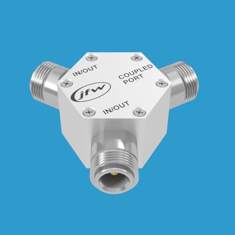
Directional Couplers
- Reactive design
- Couples in only one direction
- Provides isolation from reverse RF signals to coupled port
- Functions at specified frequency band (not at DC)
Resistive Couplers
- Resistive design
- Couples in both directions
- Functions for both DC and RF signals
-
DC Blocks (12)
DC blocks have been a staple product in JFW's line of quality RF test accessories for over 30 years. These models block DC signals and pass RF signals with minimum loss.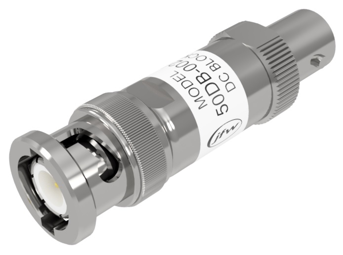 DC Blocks
DC Block Options
- 50 Ohm or 75 Ohm impedance
- Multiple RF connectors available (BNC, SMA, N, TNC, 7/16, F, reverse polarity and more)
- Breakdown Voltages up to 200 Vdc
- Frequencies up to 50 GHz
-
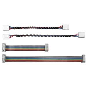
DC Cables (6)
JFW offers a line of DC cable assemblies. These 4 pin, 9 pin, and 10 pin cable assemblies can be used to interface with many of JFW's programmable attenuators and RF switches. If you have any questions about interfacing to a JFW RF component, please email our engineering department directly. For your specific application, please email JFW for assistance or use our Inquiry Form. [lt id="45"]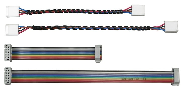 DC Cables
 -
Feedthru Terminations (4)
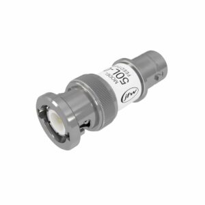
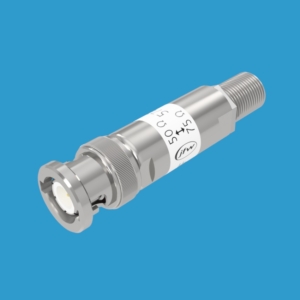
The JFW feedthru termination has been a trusted component in RF laboratories for decades. A feedthru termination is used to connect a low impedance coaxial RF cable to the high impedance inputs of test instruments (i.e. oscilloscope) and maintain proper impedance loading of the RF cable. Use a 50 Ohm feedthru termination with 50 Ohm RF cables. Use a 75 Ohm feedthru terminations with 75 Ohm RF cables. Please contact JFW for assistance or use our Inquiry Form. [lt id="73"]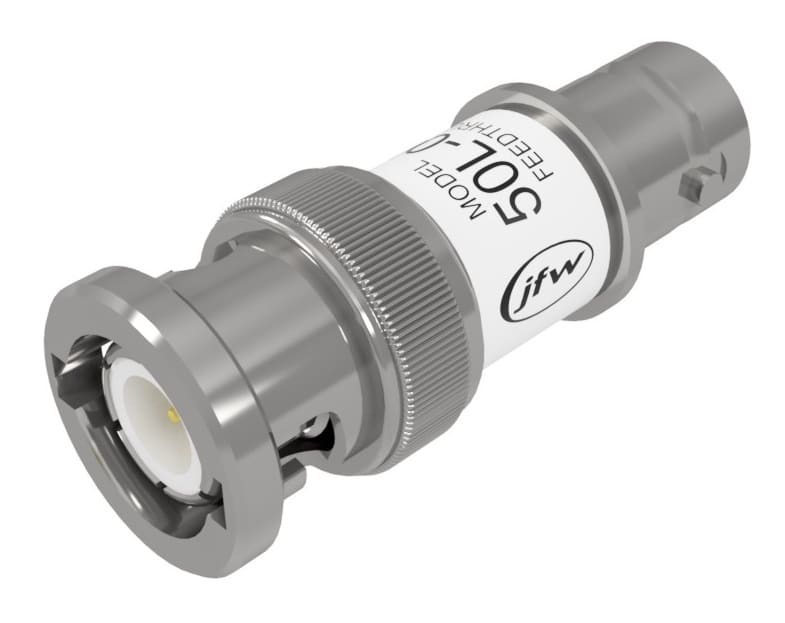 Feedthru Terminations
 -
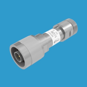
Impedance Matching Pads (3)
JFW's online Impedance matching pad models are listed in the table below. An impedance matching pad is designed using internal resistors configured to properly impedance match each side to a difference impedance. The matching pad models listed below match a 50 Ohm impedance system to a 75 Ohm impedance system. Resistive matching pads are wide-band devices that operate down to DC. For 50 Ohm to 75 Ohm impedance matching, the internal resistors do create 5.7dB of attenuation loss. If your impedance matching application must have minimum loss (i.e. < 1dB), then we recommend our impedance matching transformers instead.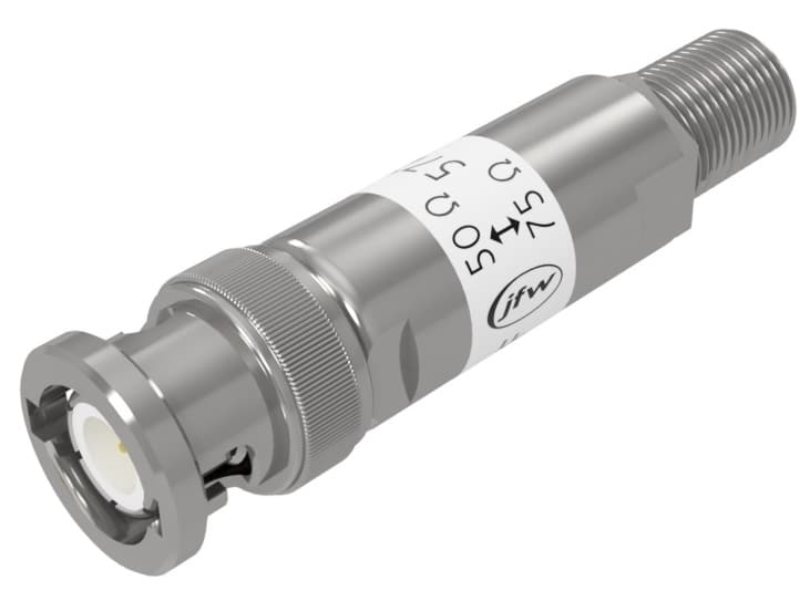 Impedance Matching Pads
Impedance Matching Pad Options
- Any RF connector combination (BNC, SMA, N, TNC, 7/16, F, reverse polarity, with bead-chains and more)
- Any impedance matched (50 Ohm, 75 Ohm, 93 Ohm, 110 Ohm, 600 Ohm and many more)
- Affordable custom models available upon request
-
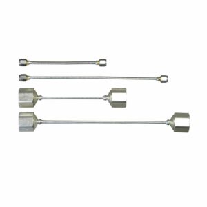
Impedance Matching Transformers (8)
JFW's online impedance matching transformer models are listed in the table below. An impedance matching transformer is a low loss device used to match two systems that have different impedance. The models below are used to match a 50 Ohm system to a 75 Ohm system. These models are bandwidth limited due to the internal reactive transformer designs.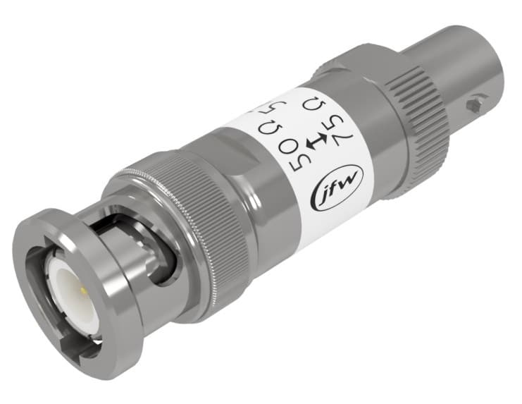 Impedance Matching Transformers
Impedance Matching Transformer Options
- Any RF connector combination (BNC, SMA, N, TNC, 7/16, F, reverse polarity, with bead-chains and more)
- Any impedance matched (50 Ohm, 75 Ohm, 93 Ohm, 100 Ohm, 125 Ohm and many more)
- Affordable custom models available upon request
-
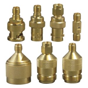
RF Adapters (30)
The RF adapter models listed below are 50 Ohm impedance coaxial RF adapters. Whether you are working at a RF test bench or building a RF sub system, JFW has RF adapters for your application. For your specific application, please contact JFW or use our Inquiry Form.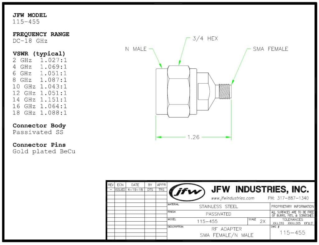 RF Adapters
RF Adapter Options:
- Panel mount models available
- 6 GHz, 18 GHz, 26.5 GHz, 40 GHz models
- Nickel or Gold Plating available
- Brass or Stainless Steel bodies available
- Reverse polarity available
Low Frequency RF Adapters
[lt id="60"]18 GHz RF Adapters
[lt id="137"]26.5 GHz RF Adapters
[lt id="138"]40 GHz RF Adapters
[lt id="139"] -
RF Cables (6)
JFW offers a line of semi-rigid coaxial RF cable assemblies. Contact the factory for additional connector combinations.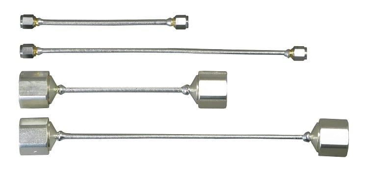 RF Cables
- RG-402 type semi-rigid RF cable
- RF cable assemblies are fully tested from DC to 6 GHz
- RF cable assemblies available with any combination of SMA or N connectors
- Choose any cable length you require
- Cable lengths are specified in inches
-
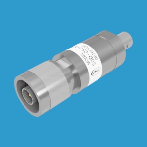
RF Detectors (5)
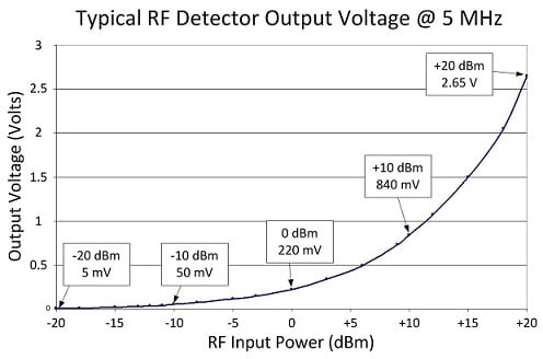
RF Detectors
JFW's online RF detector models are listed in the table below. Our RF detectors use a circuit with a zero-biased Schottky detector diode to convert the RF input signal into a DC output signal. As the amount of RF input power varies so does the DC output signal level. RF detectors are typically used for RF detection on a RF path. Insert a directional coupler into the RF path with the RF detector on the coupled port. The coupled RF signal will be converted to a DC signal by the RF detector. The DC signal can then be used by a microprocessor to determine whether RF is present on the RF path based on the amplitude of the DC signal level.- RF Detectors available with positive or negative DC outputs
- 50 Ohm and 75 Ohm impedance models available
- Various connector combinations available (i.e. N/SMA, SMA/BNC)
-
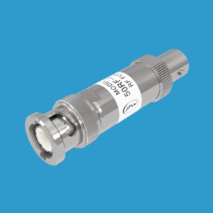
RF Fuse Holders (2)
RF fuse holders are designed to protect costly RF components and systems. These models are available with several different fusing levels (1/16A up to 1.0A). The fuses are field replaceable. The fuses are rated for 4 hours @ 100% current rating and 1 second maximum @ 200% current rating. For your specific application, please contact JFW for assistance or use our Inquiry Form. [lt id="68"] Fuse Rating at 100% rated current: 4 hours minimum Fuse Rating at 200% rated current: 1/16 A fuse @ 0.015 seconds typical 1/8 A fuse @ 0.04 seconds typical 1/4 A fuse @ 0.1 seconds typical 3/8 A fuse @ 0.1 seconds typical 1/2 A fuse @ 0.1 seconds typical 3/4 A fuse @ 0.1 seconds typical 1.0 A fuse @ 0.1 seconds typical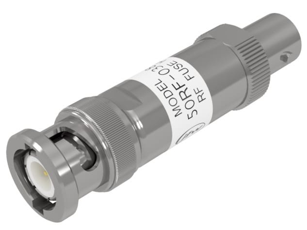 RF Fuse Holders