 Manual Handover Systems
JFW’s manual handover test systems provide a simple solution for RF testing wireless devices by combining our manual rotary attenuators and RF power divider/combiners into a convenient benchtop enclosure. All of the internal RF components are passive so no power supply is needed to operate the test systems. Simply turn the knobs to adjust each attenuator setting. Adjust a single manual attenuator to perform a signal fade test. Use two manual attenuators simultaneously to perform a manual handover test.
| JFW Model # | Impedance | Configuration | dB Total | dB Step | Frequency Start | Frequency Stop | RF Connectors |
|---|---|---|---|---|---|---|---|
| 50AA-091 | 50 Ohm | 4 x 1 Manual LC Handover System | 100 dB | 10 dB | 800 MHz | 2700 MHz | N |
| 50AA-096 | 50 Ohm | 8 x 1 Manual LC Handover System | 60 dB | 1 dB | 800 MHz | 2700 MHz | N |
| 50AA-097 | 50 Ohm | Dual 4 x 1 Manual LC Handover System | 80 dB | 1 dB | 800 MHz | 2200 MHz | SMA |
| 50AA-098 | 50 Ohm | 2 x 3 Manual LC Handover System | 70 dB | 10 dB | 800 MHz | 2700 MHz | N, SMA |
| 50AA-100 | 50 Ohm | 4 x 5 Manual LC Handover System | 70 dB | 10 dB | 800 MHz | 2700 MHz | N, SMA |
Custom Models Available
For your specific testing configuration, please use our Inquiry Form or email your block diagram to our engineering team.
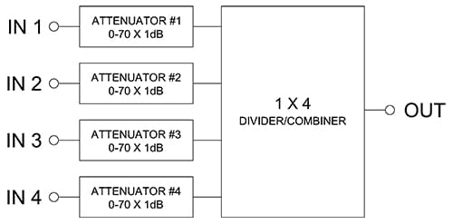
Manual 4 x 1 LC Handover System
The below block diagram is an example of a manual 4 x 1 LC handover test system. Four different communication standards (i.e. Wi-Fi, WiMAX, LTE) can be connected to the four input ports. Each communication standard can be attenuated to different levels. The output port containing all four communication standards is then connected to the handheld device.
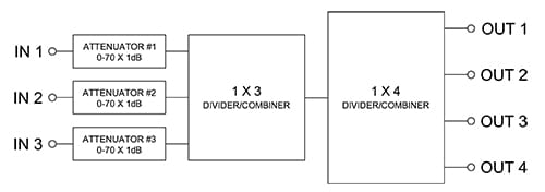
Manual 3 x 4 LC Handover System
The below block diagram is an example of a manual 3 x 4 LC handover test system. Three different communication standards (i.e. Wi-Fi, WiMAX, LTE) can be connected to the input ports. Each communication standard can be attenuated to different levels. The three communication types are combined together and then split into four signals. This configuration allows testing of four handheld devices at the same time.
- Sort by Average rating
- Display 15 Products per page
-
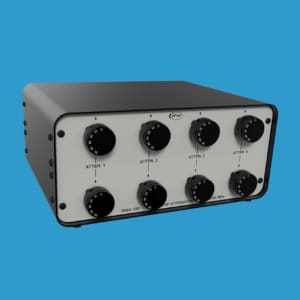
4 x 5 LC Handover System 800-2700 MHz | 50AA-100
JFW Model #: 50AA-100
Impedance: 50 Ohms
Configuration: 4 x 5 Manual LC Handover System
dB Total: 70 dB
dB Step: 10 dB
Frequency Start: 800 MHz
Frequency Stop: 2700 MHz
RF Connectors: N, SMA Female
Documentation: Data Sheet | Diagram | Drawing (N) | Drawing (SMA) -
2 x 3 LC Handover System 800-2700 MHz | 50AA-098
JFW Model #: 50AA-098
Impedance: 50 Ohms
Configuration: 2 x 3 Manual LC Handover System
dB Total: 70 dB
dB Step: 10 dB
Frequency Start: 800 MHz
Frequency Stop: 2700 MHz
RF Connectors: N, SMA Female
Documentation: Data Sheet | Diagram | Drawing -
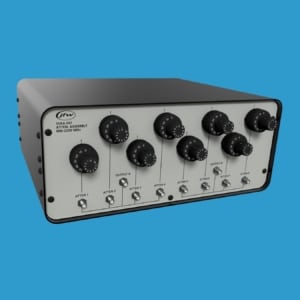
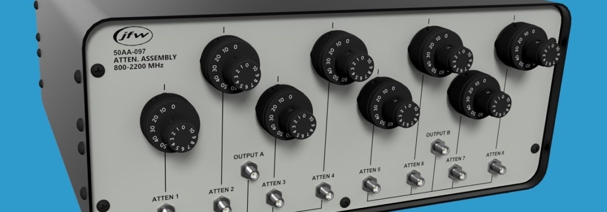
Dual 4 x 1 LC Handover System 800-2200 MHz | 50AA-097
JFW Model #: 50AA-097
Impedance: 50 Ohms
Configuration: Dual 4 x 1 Manual LC Handover System
dB Total: 80 dB
dB Step: 1 dB
Frequency Start: 800 MHz
Frequency Stop: 2200 MHz
RF Connectors: SMA Female
Documentation: Data Sheet | Diagram | Drawing -
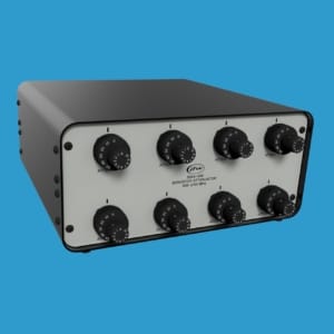
8 x 1 LC Handover System 800-2700 MHz | 50AA-096
JFW Model #: 50AA-096
Impedance: 50 Ohms
Configuration: 8 x 1 Manual LC Handover System
dB Total: 60 dB
dB Step: 1 dB
Frequency Start: 800 MHz
Frequency Stop: 2700 MHz
RF Connectors: N Female
Documentation: Data Sheet | Diagram | Drawing -
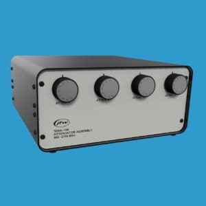
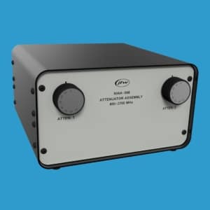
4 x 1 LC Handover System 800-2700 MHz | 50AA-091
JFW Model #: 50AA-091
Impedance: 50 Ohms
Configuration: 4 x 1 Manual LC Handover System
dB Total: 100 dB
dB Step: 10 dB
Frequency Start: 800 MHz
Frequency Stop: 2700 MHz
RF Connectors: N Female
Documentation: Data Sheet | Drawing