How does a blocking matrix switch work?
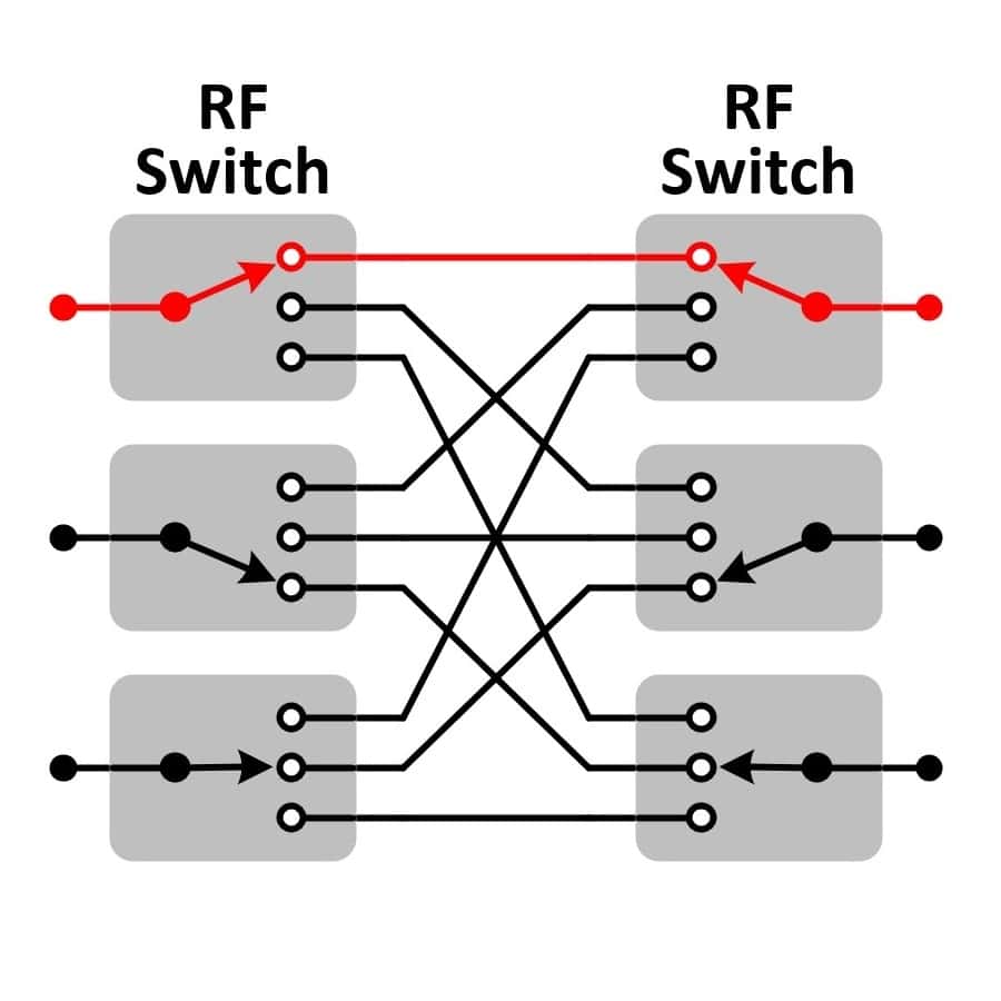
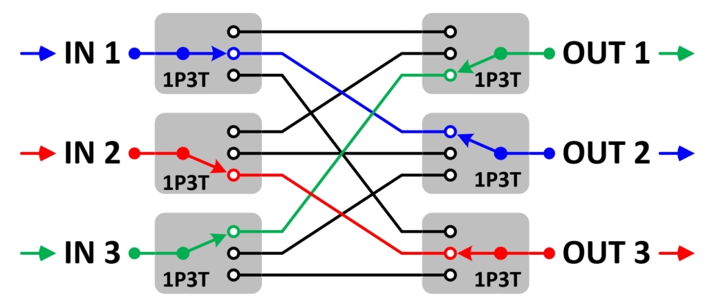
Think of a blocking matrix switch as an assembly that is built with an “input port” half and an “output port” half. Whether you use RF switches or power dividers to build each half determines how the matrix switch distributes the signals through the matrix. For a blocking matrix switch both halves are constructed using RF switches. In the block diagram below, both halves use 1P3T switches. The switch used for port IN1 is set to the switch used for port OUT2. The term “blocking matrix” is used because while port IN1 is connected to port OUT2, the port IN1 is blocked from being connected to any of the other output ports.
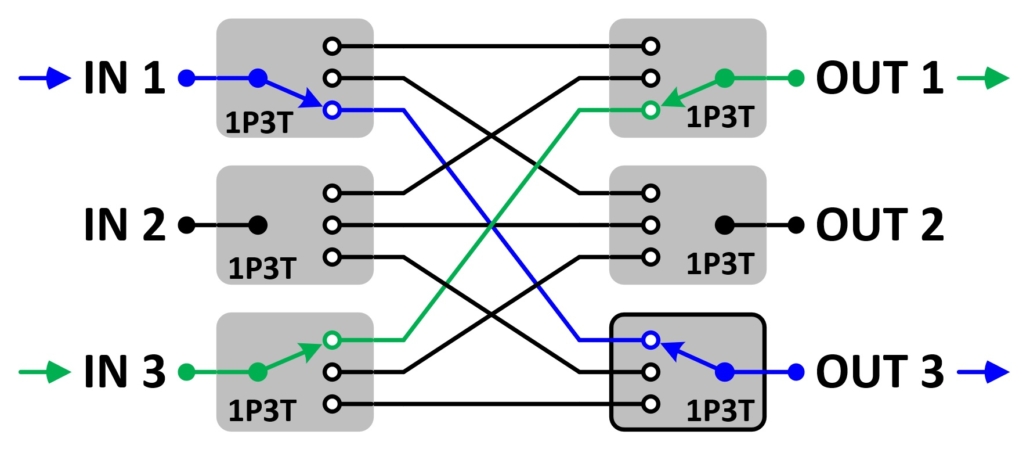
If the path setting for port IN1 is changed to OUT3, then the new path will be turned on (IN1 to OUT3) and port IN2 and port OUT2 will become unused and set to their “off” positions.
Advantages of a Blocking Matrix
- Lower insertion loss than non-blocking matrix
- Higher RF input power levels than non-blocking matrix
- High port to port isolation for both input ports and output ports
Disadvantages of a Blocking Matrix
- An input port can not connect to multiple outputs simultaneously
Maximum Number of Active Paths
For a blocking matrix switch, the maximum number of active paths is limited to the number of ports. Specifically to whichever is the smaller number: the # of input ports or the # of output ports.
3X3 blocking matrix = 3 active paths maximum
8X8 blocking matrix = 8 active paths maximum
8X4 blocking matrix = 4 active paths maximum
2X4 blocking matrix = 2 active paths maximum
Build using Electro-Mechanical Switches
If you build a blocking matrix switch using electro-mechanical RF switches you will have the lowest possible insertion loss and be able to pass though high levels of RF input power (cold switch). But electro-mechanical switches do have mechanical wear with usage and can not hot switch high RF input power. Electro-mechanical switches typically have a lifetime of 1 million settings.
Build using Solid-State Switches
If you need a blocking matrix switch for automated testing and will be switching the matrix millions of times each year, then you will need to use solid-state switches. Solid-state switches do not have any mechanical wear and have typical MTBF of > 150k hours. However, they do not handle as much RF input power as electro-mechanical switches. Solid-state switches typically can handle 1W or less of input power.
Cost Factors
Whether you build the matrix with electro-mechanical switches or solid-state switches, the cost is roughly the same. The dominate factor in matrix switch cost is the total number of ports. As you increase the number of ports, the number of internal paths increases quadratically. The best way to keep costs low is to choose a matrix switch with the minimum number of ports that you require. If you would like to see pricing for several configurations to see general costing options, JFW can provide quick ROM pricing in 1-2 days.
When you can’t use a blocking matrix switch
If your setup requires an input port to be connected to multiple output ports simultaneously, then you can not use a blocking matrix switch. For that case, you have to use a non-blocking matrix.
Available Models
JFW offers 50 Ohm blocking matrix models and 75 Ohm blocking matrix models.

