What is a RF transfer switch?
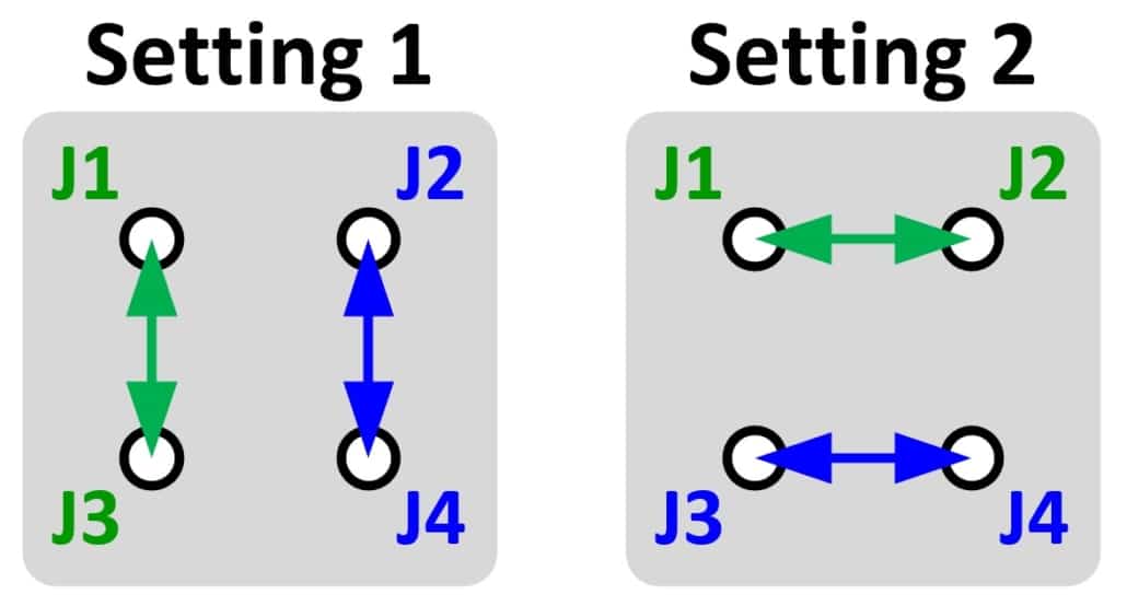
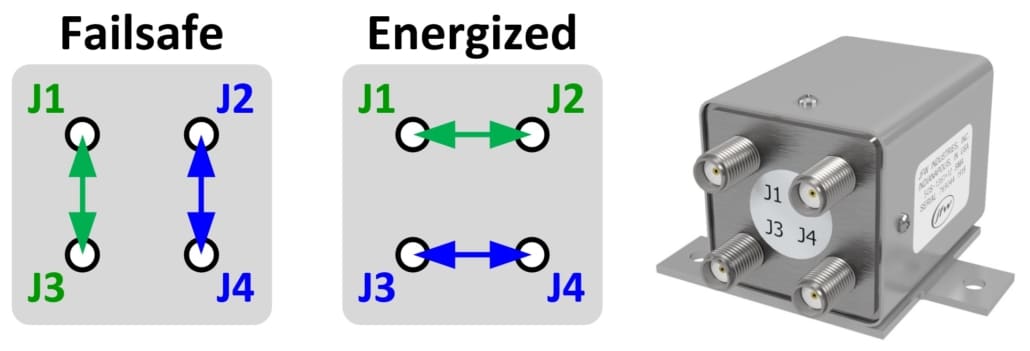
A transfer switch is a unique type of RF switch. Most RF switches have a single common port that switches between several ports i.e. 1P2T, 1P3T, 1P8T. The transfer switch does not have a single common port. Instead a transfer switch has 4 ports with two thru paths. The thru paths can be vertical like setting 1 or horizontal like setting 2. Note that there is no off state. There are always two active paths.
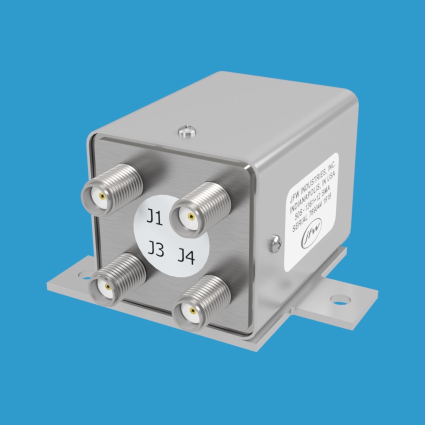
Type: Electro-mechanical Transfer Switch
JFW model 50S-1361+XX SMA is an electro-mechanical transfer switch. It has a single control line. When the control line is ground/open the switch defaults to the failsafe position. If +Vdc is applied to the control line, then it switches to the energized setting. Switches like this are popular for use in communication systems due to their failsafe capability. If power is lost to the communication system, there can still be a default/failsafe path through the system.
Use Case: Switch a RF filter in/out of test setup
A transfer switch can be used to add/remove a RF filter from a test setup. Connect the RF filter to ports J2/J4 of the transfer switch. In state 1, the transfer switch is a thru path with no filtering included in the test path. In state 2, the RF filter is switch into to the test path.
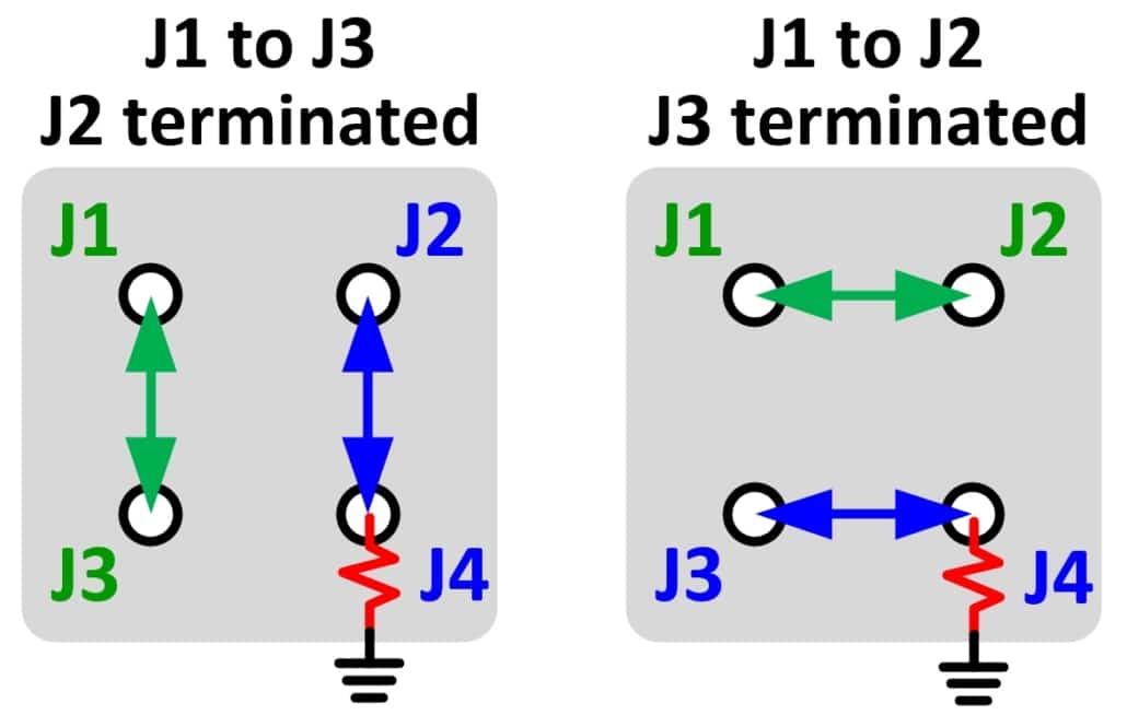
Use Case: 1P2T with high power self-termination
A transfer switch can also be used to create a self-terminating 1P2T switch. Just cable port J4 of the transfer switch to a termination. J1 acts like the common port. While ports J2 and J3 toggle between “thru path” setting and “self-terminating” setting. This is often done when the self-termination needs to be high power.