
A Day In The Life Of An RF/Microwave Attenuator
Introduction
In virtually all RF/Microwave systems the interconnect between components and response between reflective and reactive components can result in undesirable effects. Namely, impedance mismatch and VSWRs that are too high may cause standing waves between critical signal chain components that are either sensitive themselves to unintended voltage at their inputs/outputs or may otherwise result in design challenges within the signal chain. Fortunately, there are common components, specifically fixed attenuators, that are used to tackle these challenges, amongst others, and they come in a variety of ratings, shapes, styles, configurations, and performance levels.
RF/Microwave attenuators are an essential component for signal conditioning and level control tasks, which include improving VSWR (impedance match), reducing signal levels, and facilitating a variety of test and measurement setups. At the core of attenuator utility, is the ability to reduce the power of signals. This function also aids in improving impedance match between devices, such as amplifiers, mixers, and filters, that are sensitive to impedance mismatch at their ports. This article aims to educate readers on how RF fixed attenuators are used, including as a valuable tool in improving impedance match between signal chain components, and therefore improving the VSWR within the signal chain.
Impedance Match & VSWR In The Real World
Impedance mismatch is an undesirable and inevitable occurrence within and between devices, components, and interconnects within a signal chain. Most RF systems will have a designated impedance determined between components, and are often united by a given transmission line style with a designated impedance. This is commonly seen in many coaxial systems, including test systems, with a characteristic impedance of 50 Ohms. Other than this, another common coaxial transmission line impedance is 75 Ohms, though this is generally used mainly for broadcast.
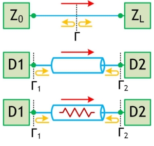
Figure 1:
Caption: (top) two devices directly connected with an impedance mismatch, (middle) two devices connected via a transmission line, (bottom) two devices connected via an inline fixed attenuator.
If the impedance between two directly connected devices (Figure 1) isn’t exactly matched, which is likely to some extent, then the impedance mismatch between the two device ports creates a reflection boundary. This reflection boundary is described using the reflection coefficient, which is a function of the differences between the two devices. In case of a transmission line, with a characteristic impedance of Z0 and a load device with an impedance at the connected port of ZL, the reflection coefficient can be determined as:
It can be observed from the previous equation that if the two impedances are matched, then the reflection coefficient is zero, while the greater the deviation between the impedances results in a higher reflection coefficient. A reflection coefficient of zero means that there is no energy lost/reflected from the junction and maximum energy transfer is achieved, a gamma of -1 is a perfect negative reflection caused by a short-circuit, and a gamma of +1 is a perfect positive reflection created by an open-circuit.
Every RF component and device has some impedance variation from connected components or transmission lines with a rated impedance. The deviation from the rated impedance at the ports is referred to as the standing-wave ratio (SWR), or voltage standing wave ratio (VSWR). VSWR is the ratio of the peak voltage to the minimum voltage of the reflected waves developed between components/devices at the rated port impedance. The VSWR of a component/device can also be calculated based on the ratio of the absolute value of the reflection coefficient plus 1 over 1 minus the absolute value of the reflection coefficient [1].
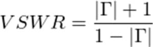
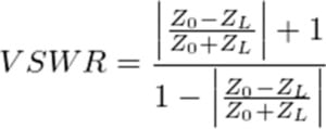
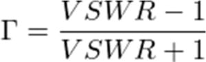
A VSWR of 1:1 is a perfect match with zero reflection, while a VSWR of inf:1 is a perfect mismatch (either open-circuit or short-circuit) with 100% energy reflection. It is generally desirable to have a VSWR as close to 1:1 as possible, although manufacturing tolerances and component/device typologies render this practically impossible. The reflection coefficient may also be written in terms of VSWR:
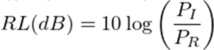
Return loss is the amount of signal energy lost from the forward signal direction due to reflections from a component/device. Typically, return loss is presented in dB of power:
As return loss can be written as a function of the reflection coefficient, and the reflection coefficient can also be written as a function of VSWR, it can be observed in the following equation that return loss is also an inverse function of VSWR:
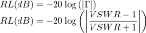
From this, we can conclude that anything that improves the return loss also improves the VSWR (i.e. increasing return loss results in a VSWR closer to 1:1, or reduced VSWR).
How Attenuators Improve Impedance Match & Reduce VSWR
A common method of mitigating the impedance mismatch between signal-chain components, or between components/devices and a transmission line, is to use a matched and fixed attenuator, sometimes referred to as a pad, between the two elements. Placing a precision attenuator at the mismatch junction causes the reflected wave to be diminished by twice the value of the attenuation. With an attenuator at the junction of a mismatch, the resulting forward wave is reduced by the value of attenuation, as well as the reflected wave.
Consequently, inserting a precision attenuator pad also results in increased return loss by twice the attenuation rating. This enhanced isolation improves the effective VSWR between the two elements of the signal chain, with the tradeoff that the forward and reverse path through the signal chain are also attenuated by the attenuation value of the precision attenuator (greater insertion loss).
In some cases a matching network may result in achieving a quality match while introducing less insertion loss into the signal chain. However, matching networks must be specifically designed for a given source and load impedance, power, frequency, and other considerations. As matching networks are so specialized, precision attenuator pads are a more readily available solution that are also generally lower in cost and require less lead time to employ. Moreover, precision fixed attenuators are designed for a flat frequency response across the entire specified frequency range, which means that they are easily inserted into a signal chain without introducing frequency-dependent level concerns, which are present with impedance matching networks.

