 Full Fan-out Handover Test Systems for Cellular Testing
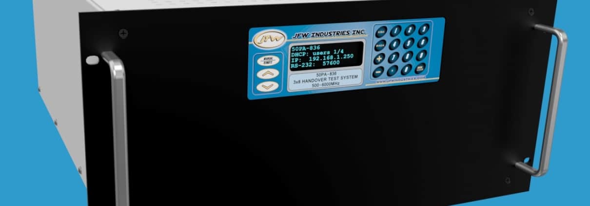
Whether you are fading multiple base station signals to a handset or testing multiple communication standards with wireless devices, JFW has a handover test system to help automate your RF testing.
JFW’s full fan-out handover test systems are a type of matrix switch that is constructed with power divider/combiners on both halves of the matrix with programmable attenuators in between. There is an individually controlled programmable attenuator on every RF path through the matrix. This type of construction allows every input signal to be available simultaneously to every output port at differently attenuated signal levels.
For assistance choosing a model, please contact JFW or use our Inquiry Form.
| JFW Model # | Impedance | Configuration | dB Total | dB Step | Frequency Start | Frequency Stop | Control | RF Connectors |
|---|---|---|---|---|---|---|---|---|
| 50PA-1022 | 50 Ohm | 6 x 6 Handover System | 63 dB | 1 dB | 20 MHz | 1000 MHz | Keypad, Ethernet, RS-232 | N, SMA, TNC |
| 50PA-539 | 50 Ohm | 4 x 4 Handover System | 95 dB | 1 dB | 2000 MHz | 6000 MHz | Keypad, Ethernet, RS-232 | N, SMA |
| 50PA-613 | 50 Ohm | 10 x 2 Handover System | 95 dB | 1 dB | 700 MHz | 6000 MHz | Keypad, Ethernet, RS-232 | N |
| 50PA-659 | 50 Ohm | 6 x 6 Handover System | 127 dB | 1 dB | 100 MHz | 1000 MHz | Keypad, Ethernet, RS-232 | N, SMA |
| 50PA-819 | 50 Ohm | 2 x 2 Handover System | 63 dB | 1 dB | 700 MHz | 6000 MHz | Keypad, Ethernet, RS-232 | N, SMA |
| 50PA-825 | 50 Ohm | 6 x 2 Handover System | 95 dB | 1 dB | 500 MHz | 6000 MHz | Keypad, Ethernet, RS-232 | N, SMA |
| 50PA-836 | 50 Ohm | 3 x 8 Handover System | 95 dB | 1 dB | 500 MHz | 6000 MHz | Keypad, Ethernet, RS-232 | N, SMA |
| 50PA-841 | 50 Ohm | 4 x 16 Handover System | 95 dB | 1 dB | 500 MHz | 6000 MHz | Keypad, Ethernet, RS-232 | N, SMA |
| 50PA-842 | 50 Ohm | 8 x 16 Handover System | 95 dB | 1 dB | 500 MHz | 6000 MHz | Keypad, Ethernet, RS-232 | N, SMA |
| 50PA-850 | 50 Ohm | 12 x 12 Handover System | 95 dB | 1 dB | 30 MHz | 3000 MHz | Keypad, Ethernet, RS-232 | N, SMA, TNC |
| 50PA-904 | 50 Ohm | 48 x 6 Handover System | 95 dB | 1 dB | 700 MHz | 3000 MHz | Keypad, Ethernet, RS-232 | N, SMA |
| 50PA-912 | 50 Ohm | 8 x 8 Handover System | 95 dB | 1 dB | 2000 MHz | 6000 MHz | Keypad, Ethernet, RS-232 | SMA |
| 50PA-947 | 50 Ohm | 4 x 4 Handover System | 95 dB | 1 dB | 500 MHz | 6000 MHz | Keypad, Ethernet, RS-232 | N, SMA |
| 50PA-948 | 50 Ohm | 4 x 2 Handover System | 95 dB | 1 dB | 500 MHz | 6000 MHz | Keypad, Ethernet, RS-232 | N, SMA |
| 50PA-950 | 50 Ohm | 4 x 8 Handover System | 95 dB | 1 dB | 500 MHz | 6000 MHz | Keypad, Ethernet, RS-232 | N, SMA |
| 50PA-969 | 50 Ohm | 8 x 8 Handover System | 95 dB | 1 dB | 698 MHz | 3000 MHz | Keypad, Ethernet, RS-232 | N, SMA |
| 50PA-979 | 50 Ohm | 6 x 8 Handover System | 95 dB | 1 dB | 698 MHz | 3000 MHz | Keypad, Ethernet, RS-232 | SMA |
| 50PA-982 | 50 Ohm | 6 x 8 Handover System | 95 dB | 1 dB | 500 MHz | 6000 MHz | Keypad, Ethernet, RS-232 | SMA |
| 50PA-983 | 50 Ohm | 8 x 8 Handover System | 95 dB | 1 dB | 500 MHz | 6000 MHz | Keypad, Ethernet, RS-232 | N, SMA |
| 50PA-1089 | 50 Ohm | 4 x 4 Handover System | 127 dB | 1 dB | 698 MHz | 3000 MHz | Keypad, Ethernet, RS-232 | N, SMA |
| 50PA-1248 | 50 Ohm | 4 x 4 Handover System | 70 dB | 1 dB | 1000 MHz | 8000 MHz | Keypad, Ethernet, RS-232 | N, SMA |
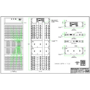
Full Fan-out Handover Test System Example
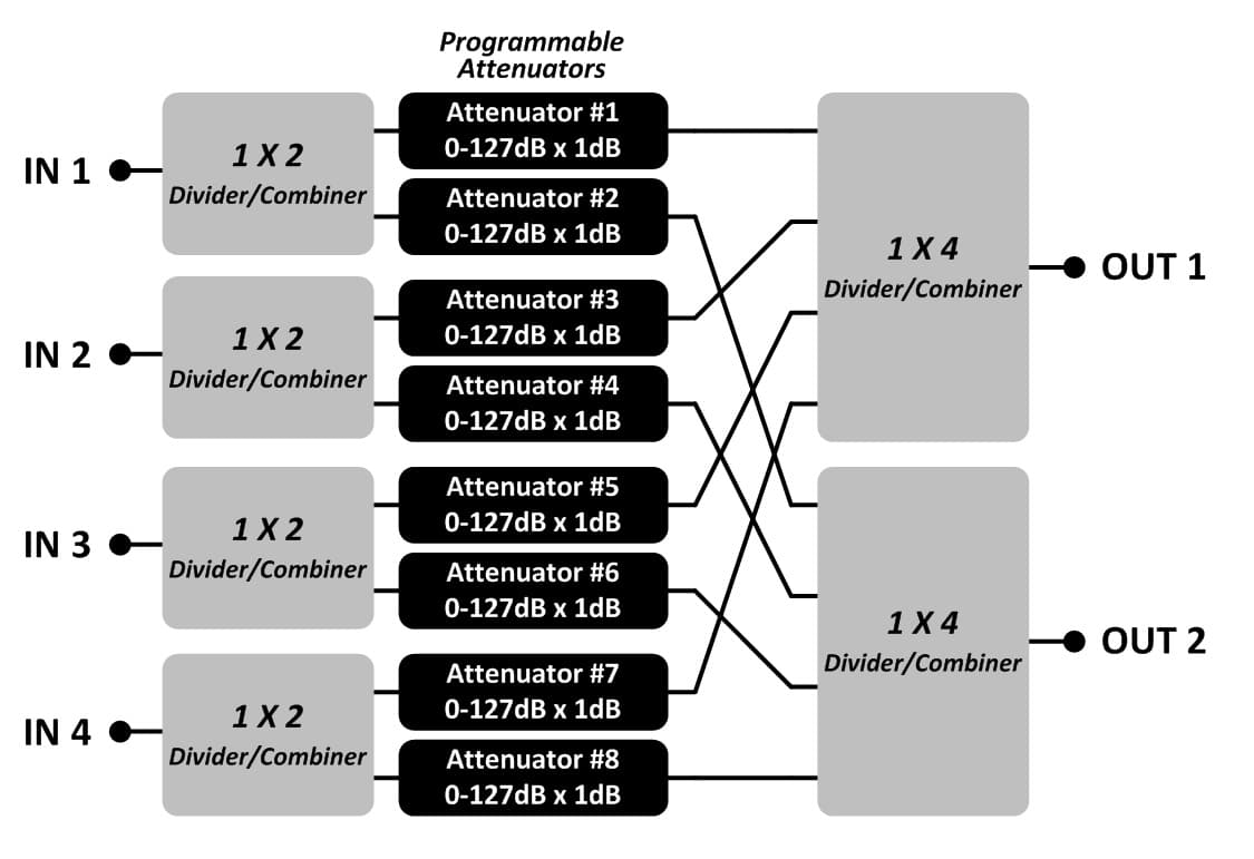
The below block diagrams show examples of a full fan-out 4 X 2 handover test system. Each path through the test system has its own individually controlled programmable attenuator. This configuration allows for each input signal to be simultaneously available to each output port at differently attenuated signal levels.
The isolation between output ports is determined by summing the isolation of the input power divider/combiner (typically 20dB for reactive type dividers) with the attenuation setting of the programmable attenuators connected to the same input port. That makes it important to keep programmable attenuators on unused paths at their maximum attenuation setting in order to maximize system isolation.
Block Diagram #1
This block diagram illustrates the construction of the full fan-out 4 x 2 handover test system. It shows all of the connectivity between the input ports and the output ports. This design allows the RF signal on input #1 to be simultaneously available to both outputs at different signal levels.
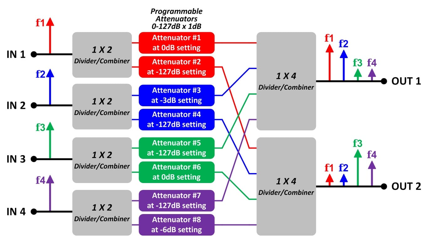
Block Diagram #2
This block diagram shows one possible setting of a full fan-out 4 x 2 handover test system. There are four input signals (red, blue, green, purple). The 1 x 2 power divider/combiners split up the input signals to both output ports. The 1 x 4 divider/combiners sum up all of the input signals for each output port.
Attenuator #1 sets f1 at 0dB of attenuation for Output #1. Attenuator #2 sets f2 at 127dB of attenuation for Output #2. The RF signal on input port #1 is simultaneously available to both output ports at different signal levels.
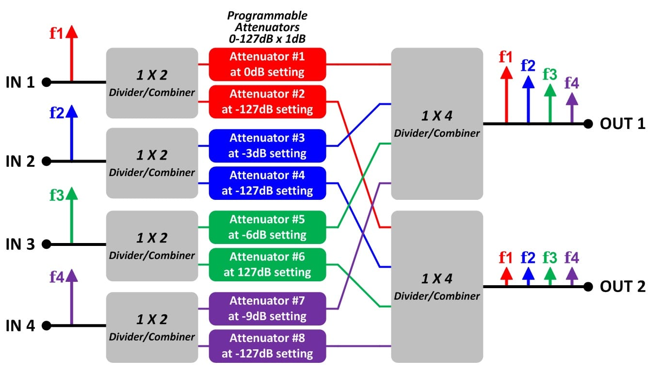
Block Diagram #3
This block diagram shows another possible setting of a full fan-out 4 x 2 handover test system. The 1 x 2 power divider/combiners split up the input signals to both output ports. The 1 x 4 divider/combiners sum up all of the input signals for each output port.
For this example the user on output port #2 has turned off all of the input signals. The user does this by setting all of the programmable attenuators connected to output #2 to their maximum attenuation setting (i.e. 127dB). The programmable attenuators connected to output port #1 are set to various attenuation settings (i.e. 0dB, 3dB, 6dB, 9dB).
Custom Models
JFW does not charge NRE’s for custom test system models. Please email us your specific requirement. We will respond with a ROM (rough order of magnitude) quote in 1-2 days.
Remote Commands
The handover test system models are available with Ethernet/Serial remote control. Our current generation of Ethernet/Serial firmware is called 3.x.x firmware. It features easy to use ASCII formatted remote commands. Use our Ethernet Test Box to demo the 3.x.x firmware.
Test Software
JFW provides a GUI test program with all Ethernet and RS-232 controlled test systems. The test software for handover test systems has all of the remote commands built in for easy testing. Jump to our sample test programs to see example programs.
- Display 30 Products per page
-
4 x 4 Handover Test System 2-6 GHz | 50PA-539
JFW Model #: 50PA-539
Impedance: 50 Ohms
Configuration: 4 x 4 Handover System
dB Total: 95 dB
dB Step: 1 dB
Frequency Start: 2000 MHz
Frequency Stop: 6 GHz
Control: Manual, Ethernet, RS-232
RF Connectors: N, SMA Female
Documentation: Data Sheet | Diagram | Drawing -
10 x 2 Handover Test System 0.7-6 GHz | 50PA-613
JFW Model #: 50PA-613
Impedance: 50 Ohms
Configuration: 10 x 2 Handover System
dB Total: 95 dB
dB Step: 1 dB
Frequency Start: 700 MHz
Frequency Stop: 6 GHz
Control: Manual, Ethernet, RS-232
RF Connectors: N Female
Documentation: Data Sheet | Diagram | Drawing -
6 x 6 Handover Test System 100-1000 MHz | 50PA-659
JFW Model #: 50PA-659
Impedance: 50 Ohms
Configuration: 6 x 6 Handover System
dB Total: 127 dB
dB Step: 1 dB
Frequency Start: 100 MHz
Frequency Stop: 1000 MHz
Control: Manual, Ethernet, RS-232
RF Connectors: N, SMA Female
Documentation: Data Sheet | Diagram | Drawing -
2 x 2 Handover Test System 0.7-6 GHz | 50PA-819
JFW Model #: 50PA-819
Impedance: 50 Ohms
Configuration: 2 x 2 Handover System
dB Total: 63 dB
dB Step: 1 dB
Frequency Start: 700 MHz
Frequency Stop: 6 GHz
Control: Manual, Ethernet, RS-232
RF Connectors: N, SMA Female
Documentation: Data Sheet | Diagram | Drawing -
6 x 2 Handover Test System 0.5-6 GHz | Model 50PA-825
JFW Model #: 50PA-825
Impedance: 50 Ohms
Configuration: 6 x 2 Handover System
dB Total: 95 dB
dB Step: 1 dB
Frequency Start: 500 MHz
Frequency Stop: 6 GHz
Control: Manual, Ethernet, RS-232
RF Connectors: N, SMA Female
Documentation: Data Sheet | Diagram | Drawing -
3 x 8 Handover Test System 0.5-6 GHz | 50PA-836
JFW Model #: 50PA-836
Impedance: 50 Ohms
Configuration: 3 x 8 Handover System
dB Total: 95 dB
dB Step: 1 dB
Frequency Start: 500 MHz
Frequency Stop: 6 GHz
Control: Manual, Ethernet, RS-232
RF Connectors: N, SMA Female
Documentation: Data Sheet | Diagram | Drawing -
4 x 16 Handover Test System 0.5-6 GHz | 50PA-841
JFW Model #: 50PA-841
Impedance: 50 Ohms
Configuration: 4 x 16 Handover System
dB Total: 95 dB
dB Step: 1 dB
Frequency Start: 500 MHz
Frequency Stop: 6 GHz
Control: Manual, Ethernet, RS-232
RF Connectors: N, SMA Female
Documentation: Data Sheet | Diagram | Drawing (N) | Drawing (SMA) -
8 x 16 Handover Test System 0.5-6 GHz | 50PA-842
JFW Model #: 50PA-842
Impedance: 50 Ohms
Configuration: 8 x 16 Handover System
dB Total: 95 dB
dB Step: 1 dB
Frequency Start: 500 MHz
Frequency Stop: 6 GHz
Control: Manual, Ethernet, RS-232
RF Connectors: N, SMA Female
Documentation: Data Sheet | Diagram | Drawing -
12 x 12 Handover Test System 30-3000 MHz | 50PA-850
JFW Model #: 50PA-850
Impedance: 50 Ohms
Configuration: 12 x 12 Handover System
dB Total: 95 dB
dB Step: 1 dB
Frequency Start: 30 MHz
Frequency Stop: 3000 MHz
Control: Manual, Ethernet, RS-232
RF Connectors: N, SMA, TNC Female
Documentation: Data Sheet | Diagram | Drawing -
48 x 6 Handover Test System 700-3000 MHz | 50PA-904
JFW Model #: 50PA-904
Impedance: 50 Ohms
Configuration: 48 x 6 Handover System
dB Total: 95 dB
dB Step: 1 dB
Frequency Start: 700 MHz
Frequency Stop: 3000 MHz
Control: Manual, Ethernet, RS-232
RF Connectors: N, SMA Female
Documentation: Data Sheet | Diagram | Drawing -
8 x 8 Handover Test System 2-6 GHz | 50PA-912
JFW Model #: 50PA-912
Impedance: 50 Ohms
Configuration: 8 x 8 Handover System
dB Total: 95 dB
dB Step: 1 dB
Frequency Start: 2000 MHz
Frequency Stop: 6 GHz
Control: Manual, Ethernet, RS-232
RF Connectors: SMA Female
Documentation: Data Sheet | Diagram | Drawing -
4 x 4 Handover Test System 0.5-6 GHz | 50PA-947
JFW Model #: 50PA-947
Impedance: 50 Ohms
Configuration: 4 x 4 Handover System
dB Total: 95 dB
dB Step: 1 dB
Frequency Start: 500 MHz
Frequency Stop: 6 GHz
Control: Manual, Ethernet, RS-232
RF Connectors: N, SMA Female
Documentation: Data Sheet | Diagram | Drawing (N) | Drawing (SMA) -
4 x 2 Handover Test System 0.5-6 GHz | 50PA-948
JFW Model #: 50PA-948
Impedance: 50 Ohms
Configuration: 4 x 2 Handover System
dB Total: 95 dB
dB Step: 1 dB
Frequency Start: 500 MHz
Frequency Stop: 6 GHz
Control: Manual, Ethernet, RS-232
RF Connectors: N, SMA Female
Documentation: Data Sheet | Diagram | Drawing (N) | Drawing (SMA) -
4 x 8 Handover Test System 0.5-6 GHz | 50PA-950
JFW Model #: 50PA-950
Impedance: 50 Ohms
Configuration: 4 x 8 Handover System
dB Total: 95 dB
dB Step: 1 dB
Frequency Start: 500 MHz
Frequency Stop: 6 GHz
Control: Manual, Ethernet, RS-232
RF Connectors: N, SMA Female
Documentation: Data Sheet | Diagram | Drawing -
8 x 8 Handover Test System 698-3000 MHz | 50PA-969
JFW Model #: 50PA-969
Impedance: 50 Ohms
Configuration: 8 x 8 Handover System
dB Total: 95 dB
dB Step: 1 dB
Frequency Start: 698 MHz
Frequency Stop: 3000 MHz
Control: Manual, Ethernet, RS-232
RF Connectors: N, SMA Female
Documentation: Data Sheet | Diagram | Drawing (N) | Drawing (SMA) -
6 x 8 Handover Test System 698-3000 MHz | 50PA-979
JFW Model #: 50PA-979
Impedance: 50 Ohms
Configuration: 6 x 8 Handover System
dB Total: 95 dB
dB Step: 1 dB
Frequency Start: 698 MHz
Frequency Stop: 3000 MHz
Control: Manual, Ethernet, RS-232
RF Connectors: SMA Female
Documentation: Data Sheet | Diagram | Drawing -
6 x 8 Handover Test System 0.5-6 GHz | 50PA-982
JFW Model #: 50PA-982
Impedance: 50 Ohms
Configuration: 6 x 8 Handover System
dB Total: 95 dB
dB Step: 1 dB
Frequency Start: 500 MHz
Frequency Stop: 6 GHz
Control: Manual, Ethernet, RS-232
RF Connectors: SMA Female
Documentation: Data Sheet | Diagram | Drawing -
8 x 8 Handover Test System 0.5-6 GHz | 50PA-983
JFW Model #: 50PA-983
Impedance: 50 Ohms
Configuration: 8 x 8 Handover System
dB Total: 95 dB
dB Step: 1 dB
Frequency Start: 500 MHz
Frequency Stop: 6 GHz
Control: Manual, Ethernet, RS-232
RF Connectors: N or SMA Female
Documentation: Data Sheet | Diagram | Drawing -
6 x 6 Handover Test System 20-1000 MHz | 50PA-1022
JFW Model #: 50PA-1022
Impedance: 50 Ohms
Configuration: 6 x 6 Handover System
dB Total: 63 dB
dB Step: 1 dB
Frequency Start: 20 MHz
Frequency Stop: 1000 MHz
Control: Manual, Ethernet, RS-232
RF Connectors: N, SMA, TNC Female
Documentation: Data Sheet | Diagram | Drawing -
4 x 4 Handover Test System 698-3000 MHz | 50PA-1089
JFW Model #: 50PA-1089
Impedance: 50 Ohms
Configuration: 4 x 4 Handover System
dB Total: 127 dB
dB Step: 1 dB
Frequency Start: 698 MHz
Frequency Stop: 3 GHz
Manual Control: Display and Keyboard
Remote Control: Ethernet and RS-232
RF Connectors: N, SMA Female
Documentation: Data Sheet | Drawing | Diagram -
4 x 4 Handover Test System 1-8 GHz | 50PA-1248
JFW Model #: 50PA-1248
Impedance: 50 Ohms
Configuration: 4 x 4 Handover System
dB Total: 70 dB
dB Step: 1 dB
Frequency Start: 1000 MHz
Frequency Stop: 8000 MHz
Manual Control: Display and Keyboard
Remote Control: Ethernet and RS-232
RF Connectors: N, SMA Female
Documentation: Data Sheet | Drawing | Diagram