Handover Test Systems for Cellular Testing
Family of handover test systems designed for handset-to-network handover testing. Internal step attenuators allow the RF signal between the network access points and the handsets to be dynamically faded up/down. The Ethernet/Serial models run our latest generation 3.x.x firmware that features easy to use ASCII formatted commands.
- Full fan-out models provide the greatest testing flexibility with individually controlled step attenuator on every RF path thru the matrix.
- Limited fan-out models use a common highway configuration which reduces the number of internal paths and the number of attenuators.
- Manual handover models use manually controlled attenuators for simple benchtop testing.
- Display 15 Products per page
-
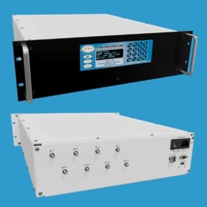
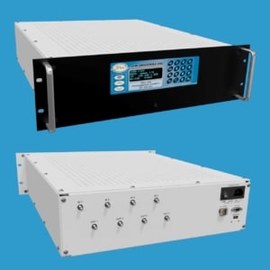
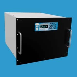
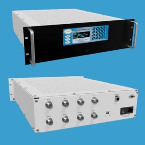
4 x 4 Handover Test System 1-8 GHz | 50PA-1248
JFW Model #: 50PA-1248
Impedance: 50 Ohms
Configuration: 4 x 4 Handover System
dB Total: 70 dB
dB Step: 1 dB
Frequency Start: 1000 MHz
Frequency Stop: 8000 MHz
Manual Control: Display and Keyboard
Remote Control: Ethernet and RS-232
RF Connectors: N, SMA Female
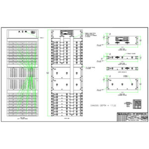
Documentation: Data Sheet | Drawing | Diagram -
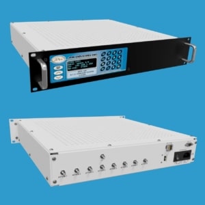
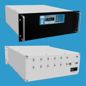
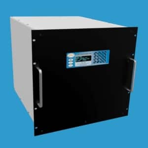
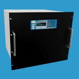
8 x 1 LC Handover Test System 2-8 GHz | 50PA-1241
JFW Model #: 50PA-1241
Impedance: 50 Ohms
Configuration: 8 x 1 LC Handover System
dB Total: 95 dB
dB Step: 1 dB
Frequency Start: 2 GHz
Frequency Stop: 8 GHz
Manual Control: Display and Keyboard
Remote Control: Ethernet and RS-232
RF Connectors: N or SMA Female
Documentation: Data Sheet | Drawing | Diagram -
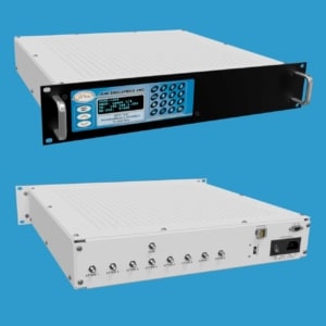
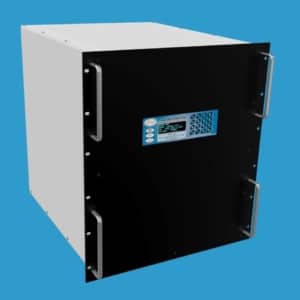
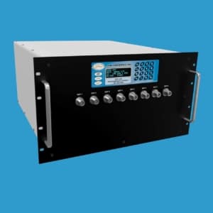
8 x 1 LC Handover Test System 30-6000 MHz | 50PA-1205
JFW Model #: 50PA-1205
Impedance: 50 Ohms
Configuration: 8 x 1 LC Handover System
dB Total: 95 dB
dB Step: 1 dB
Frequency Start: 30 MHz
Frequency Stop: 6 GHz
Manual Control: Display and Keyboard
Remote Control: Ethernet and RS-232
RF Connectors: N, SMA Female
Documentation: Data Sheet | Drawing | Diagram -
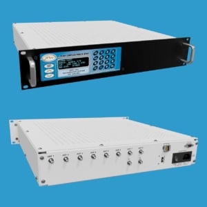
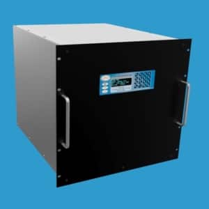
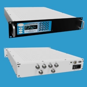
8 x 2 LC Handover Test System 698-3000 MHz | 50PA-1091
JFW Model #: 50PA-1091
Impedance: 50 Ohms
Configuration: 8 x 2 LC Handover System
dB Total: 127 dB
dB Step: 1 dB
Frequency Start: 698 MHz
Frequency Stop: 3 GHz
Manual Control: Display and Keyboard
Remote Control: Ethernet and RS-232
RF Connectors: N, SMA Female
Documentation: Data Sheet | Drawing | Diagram -
4 x 4 Handover Test System 698-3000 MHz | 50PA-1089
JFW Model #: 50PA-1089
Impedance: 50 Ohms
Configuration: 4 x 4 Handover System
dB Total: 127 dB
dB Step: 1 dB
Frequency Start: 698 MHz
Frequency Stop: 3 GHz
Manual Control: Display and Keyboard
Remote Control: Ethernet and RS-232
RF Connectors: N, SMA Female
Documentation: Data Sheet | Drawing | Diagram -
6 x 6 Handover Test System 20-1000 MHz | 50PA-1022
JFW Model #: 50PA-1022
Impedance: 50 Ohms
Configuration: 6 x 6 Handover System
dB Total: 63 dB
dB Step: 1 dB
Frequency Start: 20 MHz
Frequency Stop: 1000 MHz
Control: Manual, Ethernet, RS-232
RF Connectors: N, SMA, TNC Female
Documentation: Data Sheet | Diagram | Drawing -
8 x 8 Handover Test System 0.5-6 GHz | 50PA-983
JFW Model #: 50PA-983
Impedance: 50 Ohms
Configuration: 8 x 8 Handover System
dB Total: 95 dB
dB Step: 1 dB
Frequency Start: 500 MHz
Frequency Stop: 6 GHz
Control: Manual, Ethernet, RS-232
RF Connectors: N or SMA Female
Documentation: Data Sheet | Diagram | Drawing -
6 x 8 Handover Test System 0.5-6 GHz | 50PA-982
JFW Model #: 50PA-982
Impedance: 50 Ohms
Configuration: 6 x 8 Handover System
dB Total: 95 dB
dB Step: 1 dB
Frequency Start: 500 MHz
Frequency Stop: 6 GHz
Control: Manual, Ethernet, RS-232
RF Connectors: SMA Female
Documentation: Data Sheet | Diagram | Drawing -
6 x 8 Handover Test System 698-3000 MHz | 50PA-979
JFW Model #: 50PA-979
Impedance: 50 Ohms
Configuration: 6 x 8 Handover System
dB Total: 95 dB
dB Step: 1 dB
Frequency Start: 698 MHz
Frequency Stop: 3000 MHz
Control: Manual, Ethernet, RS-232
RF Connectors: SMA Female
Documentation: Data Sheet | Diagram | Drawing -
8 x 8 Handover Test System 698-3000 MHz | 50PA-969
JFW Model #: 50PA-969
Impedance: 50 Ohms
Configuration: 8 x 8 Handover System
dB Total: 95 dB
dB Step: 1 dB
Frequency Start: 698 MHz
Frequency Stop: 3000 MHz
Control: Manual, Ethernet, RS-232
RF Connectors: N, SMA Female
Documentation: Data Sheet | Diagram | Drawing (N) | Drawing (SMA) -
4 x 8 Handover Test System 0.5-6 GHz | 50PA-950
JFW Model #: 50PA-950
Impedance: 50 Ohms
Configuration: 4 x 8 Handover System
dB Total: 95 dB
dB Step: 1 dB
Frequency Start: 500 MHz
Frequency Stop: 6 GHz
Control: Manual, Ethernet, RS-232
RF Connectors: N, SMA Female
Documentation: Data Sheet | Diagram | Drawing -
4 x 2 Handover Test System 0.5-6 GHz | 50PA-948
JFW Model #: 50PA-948
Impedance: 50 Ohms
Configuration: 4 x 2 Handover System
dB Total: 95 dB
dB Step: 1 dB
Frequency Start: 500 MHz
Frequency Stop: 6 GHz
Control: Manual, Ethernet, RS-232
RF Connectors: N, SMA Female
Documentation: Data Sheet | Diagram | Drawing (N) | Drawing (SMA) -
4 x 4 Handover Test System 0.5-6 GHz | 50PA-947
JFW Model #: 50PA-947
Impedance: 50 Ohms
Configuration: 4 x 4 Handover System
dB Total: 95 dB
dB Step: 1 dB
Frequency Start: 500 MHz
Frequency Stop: 6 GHz
Control: Manual, Ethernet, RS-232
RF Connectors: N, SMA Female
Documentation: Data Sheet | Diagram | Drawing (N) | Drawing (SMA) -
8 x 8 Handover Test System 2-6 GHz | 50PA-912
JFW Model #: 50PA-912
Impedance: 50 Ohms
Configuration: 8 x 8 Handover System
dB Total: 95 dB
dB Step: 1 dB
Frequency Start: 2000 MHz
Frequency Stop: 6 GHz
Control: Manual, Ethernet, RS-232
RF Connectors: SMA Female
Documentation: Data Sheet | Diagram | Drawing -
48 x 6 Handover Test System 700-3000 MHz | 50PA-904
JFW Model #: 50PA-904
Impedance: 50 Ohms
Configuration: 48 x 6 Handover System
dB Total: 95 dB
dB Step: 1 dB
Frequency Start: 700 MHz
Frequency Stop: 3000 MHz
Control: Manual, Ethernet, RS-232
RF Connectors: N, SMA Female
Documentation: Data Sheet | Diagram | Drawing