 Non-Blocking Matrix Switches
 Non-Blocking Matrix Switches
A non-blocking matrix switch is constructed with power dividers on the input ports and RF switches on the output ports. This configuration allows an input port to be connected to multiple output ports simultaneously.
The advantage of a non-blocking matrix over a blocking matrix is its greater connection flexibility. An input port is always available to be connected to any output port. However, the power dividers cause a non-blocking matrix to have greater insertion loss than a blocking matrix. The power dividers also decrease the isolation between output channels. In the event that two output ports are switched to receive the same input signal, the isolation between output ports is determined by the isolation of the power divider. Our RF Matrix Guide steps through the advantages for each matrix switch type. For your specific application, please contact our engineering department for recommendations.
50 Ohm Models
| JFW Model # | Impedance | Configuration | Unused Ports | Frequency Start | Frequency Stop | RF Input Power | RF Connectors |
|---|---|---|---|---|---|---|---|
| 50MS-287 | 50 Ohm | 24 x 4 Non-Blocking Matrix Switch | Absorptive | 20 MHz | 2 GHz | +20 dBm | N, SMA |
| 50MS-288 | 50 Ohm | 8 x 8 Non-Blocking Matrix Switch | Absorptive | 20 MHz | 1 GHz | +20 dBm | N |
| 50MS-299 | 50 Ohm | 8 x 4 Non-Blocking Matrix Switch | Absorptive | 700 MHz | 3 GHz | +20 dBm | SMA |
| 50MS-300 | 50 Ohm | 8 x 8 Non-Blocking Matrix Switch | Absorptive | 700 MHz | 3 GHz | +20 dBm | SMA |
| 50MS-304 | 50 Ohm | 6 x 6 Non-Blocking Matrix Switch | Absorptive | 2000 MHz | 6 GHz | +20 dBm | SMA |
| 50MS-313 | 50 Ohm | 4 x 4 Non-Blocking Matrix Switch | Absorptive | 700 MHz | 3 GHz | +30 dBm | N |
| 50MS-335 | 50 Ohm | 8 x 16 Non-Blocking Matrix Switch | Absorptive | 700 MHz | 3 GHz | +20 dBm | SMA |
| 50MS-420 | 50 Ohm | 16 x 16 Non-Blocking Matrix Switch | Absorptive | 20 MHz | 3 GHz | +30 dBm | N, SMA |
| 50MS-423 | 50 Ohm | 24 x 12 Non-Blocking Matrix Switch | Absorptive | 700 MHz | 4 GHz | +30 dBm | SMA |
| 50MS-426 | 50 Ohm | 8 x 8 Non-Blocking Matrix Switch | Absorptive | 350 MHz | 6 GHz | +30 dBm | N, SMA |
| 50MS-435 | 50 Ohm | 4 x 6 Non-Blocking Matrix Switch | IN absorptive, OUT reflective | 1000 MHz | 18 GHz | +30 dBm | N, SMA |
| 50MS-436 | 50 Ohm | 4 x 8 Non-Blocking Matrix Switch | IN absorptive, OUT reflective | 1000 MHz | 18 GHz | +30 dBm | N, SMA |
| 50MS-437 | 50 Ohm | 8 x 8 Non-Blocking Matrix Switch | IN absorptive, OUT reflective | 1000 MHz | 18 GHz | +30 dBm | N, SMA |
| 50MS-460 | 50 Ohm | 4 x 4 Non-Blocking Matrix Switch | Absorptive | 350 MHz | 6 GHz | +30 dBm | N, SMA |
| 50MS-462 | 50 Ohm | 4 x 4 Non-Blocking Matrix Switch | Absorptive | 500 MHz | 8.4 GHz | +30 dBm | N, SMA |
| 50MS-463 | 50 Ohm | 8 x 8 Non-Blocking Matrix Switch | Absorptive | 500 MHz | 8.4 GHz | +30 dBm | N, SMA |
| 50MS-465 | 50 Ohm | 4 x 4 Non-Blocking Matrix Switch | IN absorptive, OUT reflective | 1000 MHz | 18 GHz | +30 dBm | N, SMA |
75 Ohm Models
| JFW Model # | Impedance | Configuration | Unused Ports | Frequency Start | Frequency Stop | RF Input Power | RF Connectors |
|---|---|---|---|---|---|---|---|
| 75MS-052 | 75 Ohm | 8 x 8 Non-Blocking Matrix Switch | Absorptive | 5 MHz | 1218 MHz | +20 dBm | F |
| 75MS-040 | 75 Ohm | 4 x 4 Non-Blocking RF Matrix Switch | Absorptive | 5 MHz | 2150 MHz | +10 dBm | F |
| 75MS-050 | 75 Ohm | 4 x 4 Non-Blocking RF Matrix Switch | Absorptive | 5 MHz | 1218 MHz | +20 dBm | F |
| 75MS-051 | 75 Ohm | 4 x 8 Non-Blocking RF Matrix Switch | Absorptive | 5 MHz | 1218 MHz | +20 dBm | F |
Maximum Active RF Path Examples
3 x 3 Non-Blocking Matrix with output ports built as switches: 3 active paths maximum
8 x 4 Non-Blocking Matrix with output ports built as switches: 4 active paths maximum
4 x 8 Non-Blocking Matrix with output ports built as switches: 8 active paths maximum
2 x 4 Non-Blocking Matrix with output ports built as switches: 4 active paths maximum
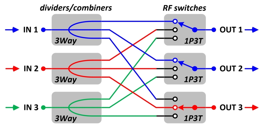
Example Diagram #1
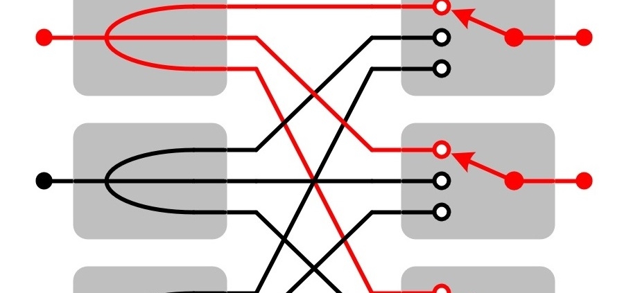
This block diagram shows one possible setting of a 3 X 3 non-blocking matrix switch. There are three input signals (blue, red, green). The power dividers split up the input signals so that each input signal is available to all output ports at all times. The switches limit the matrix to having only three active paths.
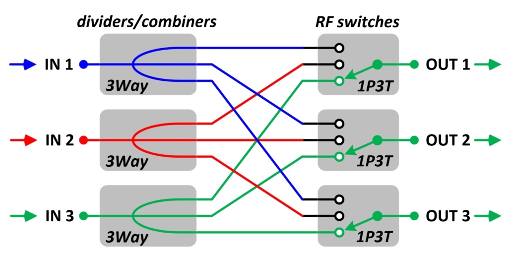
Example Diagram #2
This block diagram shows another possible setting of a 3 X 3 non-blocking matrix switch. Input 3 is connected to all output ports simultaneously.
Custom Models
JFW does not charge NRE’s for custom test system models. Please email us your specific requirement. We will respond with a ROM (rough order of magnitude) quote in 1-2 days.
Remote Commands
The matrix switches are available with Ethernet/Serial remote control. Our current generation of Ethernet/Serial firmware is called 3.x.x firmware. It features easy to use ASCII formatted remote commands. Use our Ethernet Test Box to demo the 3.x.x firmware.
Test Software
JFW provides a GUI test program with all Ethernet and RS-232 controlled test systems. The test software for matrix switches has all of the remote commands built in for easy testing. Jump to our sample test programs to see example programs.
- Display 15 Products per page
-

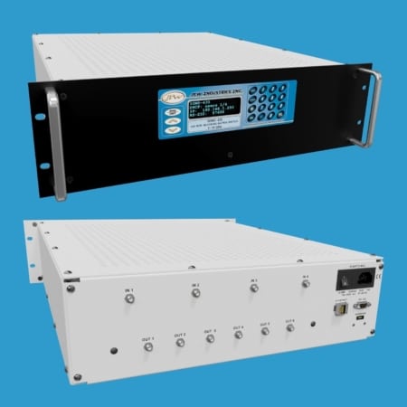
50MS-287 | 24×4 Non-Blocking Matrix Switch
JFW Model #: 50MS-287
Impedance: 50 Ohm
Configuration: 24 x 4 Non-Blocking Matrix Switch
Frequency Range: 20-2000 MHz
Switch Type: Solid-state
Unused Ports: Absorptive
RF Input Power: +20 dBm
RF Connectors: N, SMA
Documentation: Data Sheet | Diagram | Drawing -
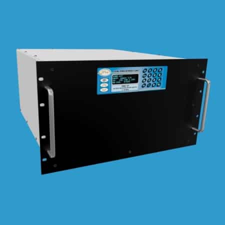
50MS-288 | 8×8 Non-Blocking Matrix Switch
JFW Model #: 50MS-288
Impedance: 50 Ohm
Configuration: 8 x 8 Non-Blocking Matrix Switch
Frequency Range: 20-1000 MHz
Switch Type: Solid-state
Unused Ports: Absorptive
RF Input Power: +20 dBm
RF Connectors: BNC, N, SMA, TNC
Documentation: Data Sheet | Diagram | Drawing -
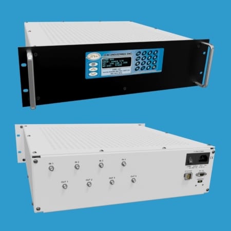
50MS-299 | 8×4 Non-Blocking Matrix Switch
JFW Model #: 50MS-299
Impedance: 50 Ohm
Configuration: 8 x 4 Non-Blocking Matrix Switch
Frequency Range: 700-3000 MHz
Switch Type: Solid-state
Unused Ports: Absorptive
RF Input Power: +20 dBm
RF Connectors: SMA
Documentation: Data Sheet | Diagram | Drawing | Drawing -
50MS-300 | 8×8 Non-Blocking Matrix Switch
JFW Model #: 50MS-300
Impedance: 50 Ohm
Configuration: 8 x 8 Non-Blocking Matrix Switch
Frequency Range: 700-3000 MHz
Switch Type: Solid-state
Unused Ports: Absorptive
RF Input Power: +20 dBm
RF Connectors: SMA
Documentation: Data Sheet | Diagram | Drawing -
50MS-304 | 6×6 Non-Blocking Matrix Switch
JFW Model #: 50MS-304
Impedance: 50 Ohm
Configuration: 6 x 6 Non-Blocking Matrix Switch
Frequency Range: 2-6 GHz
Switch Type: Solid-state
Unused Ports: Absorptive
RF Input Power: +20 dBm
RF Connectors: SMA
Documentation: Data Sheet | Diagram | Drawing -
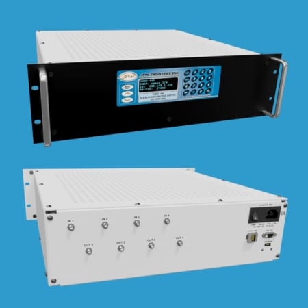
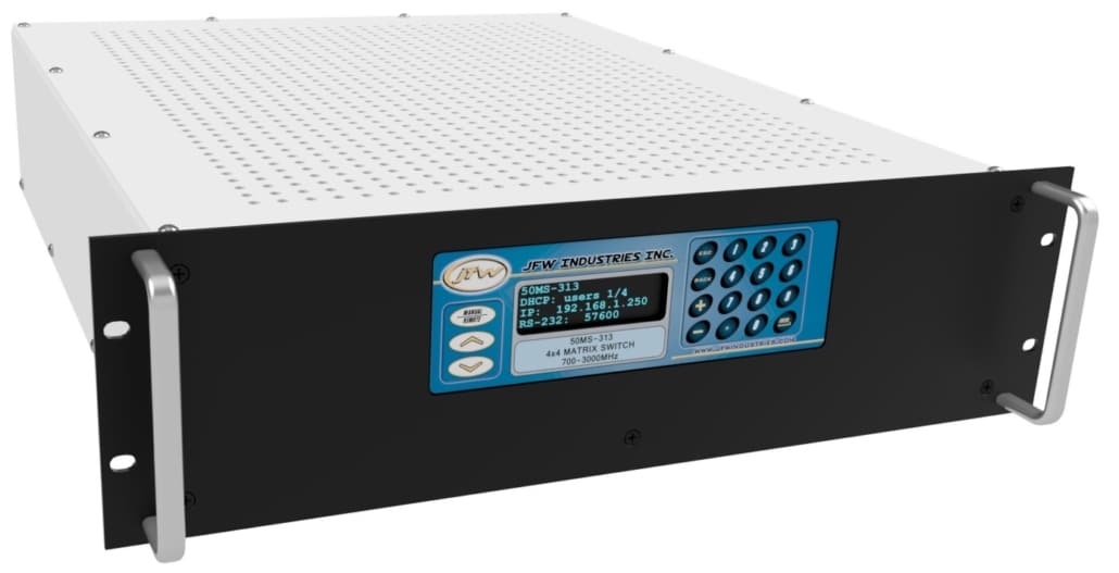
50MS-313 | 4×4 Non-Blocking Matrix Switch
JFW Model #: 50MS-313
Impedance: 50 Ohm
Configuration: 4 x 4 Non-Blocking Matrix Switch
Frequency Range: 700-3000 MHz
Switch Type: Solid-state
Unused Ports: Absorptive
RF Input Power: +30 dBm
RF Connectors: N
Documentation: Data Sheet | Diagram | Drawing -
50MS-335 | 8×16 Non-Blocking Matrix Switch
JFW Model #: 50MS-336
Impedance: 50 Ohm
Configuration: 8 x 16 Non-Blocking Matrix Switch
Frequency Range: 700-3000 MHz
Switch Type: Solid-state
Unused Ports: Absorptive
RF Input Power: +20 dBm
RF Connectors: SMA
Documentation: Data Sheet | Diagram | Drawing -
50MS-420 | 16×16 Non-Blocking Matrix Switch
JFW Model #: 50MS-420
Impedance: 50 Ohm
Configuration: 16 x 16 Non-Blocking Matrix Switch
Frequency Range: 20-3000 MHz
Switch Type: Solid-state
Unused Ports: Absorptive
RF Input Power: +30 dBm
RF Connectors: N, SMA
Documentation: Data Sheet | Diagram | Drawing -
50MS-423 | 24×12 Non-Blocking Matrix Switch
JFW Model #: 50MS-423
Impedance: 50 Ohm
Configuration: 24 x 12 Non-Blocking Matrix Switch
Frequency Range: 700-4000 MHz
Switch Type: Solid-state
Unused Ports: Absorptive
RF Input Power: +30 dBm
RF Connectors: SMA
Documentation: Data Sheet | Diagram | Drawing -
50MS-426 | 8×8 Non-Blocking Matrix Switch
JFW Model #: 50MS-426
Impedance: 50 Ohm
Configuration: 8 x 8 Non-Blocking Matrix Switch
Frequency Range: 350-6000 MHz
Switch Type: Solid-state
Unused Ports: Absorptive
RF Input Power: +30 dBm
RF Connectors: N, SMA
Documentation: Data Sheet | Diagram | Drawing -

50MS-435 | 4×6 Non-Blocking Matrix Switch
JFW Model #: 50MS-435
Impedance: 50 Ohm
Configuration: 4 x 6 Non-Blocking Matrix Switch
Frequency Range: 1-18 GHz
Switch Type: Solid-state
Unused IN Ports: Absorptive
Unused OUT Ports: Reflective
RF Input Power: +30 dBm
RF Connectors: N or SMA
Documentation: Data Sheet | Drawing | Diagram -
50MS-436 | 4×8 Non-Blocking Matrix Switch
JFW Model #: 50MS-436
Impedance: 50 Ohm
Configuration: 4 x 8 Non-Blocking Matrix Switch
Frequency Range: 1-18 GHz
Switch Type: Solid-state
Unused IN Ports: Absorptive
Unused OUT Ports: Reflective
RF Input Power: +30 dBm
RF Connectors: N or SMA
Documentation: Data Sheet | Drawing | Diagram -
50MS-437 | 8×8 Non-Blocking Matrix Switch
JFW Model #: 50MS-437
Impedance: 50 Ohm
Configuration: 8 x 8 Non-Blocking Matrix Switch
Frequency Range: 1-18 GHz
Switch Type: Solid-state
Unused IN Ports: Absorptive
Unused OUT Ports: Reflective
RF Input Power: +30 dBm
RF Connectors: N or SMA
Documentation: Data Sheet | Drawing | Diagram -
50MS-460 | 4×4 Non-Blocking Matrix Switch
JFW Model #: 50MS-460
Impedance: 50 Ohm
Configuration: 4 x 4 Non-Blocking Matrix Switch
Frequency Range: 350-6000 MHz
Switch Type: Solid-state
Unused Ports: Absorptive
RF Input Power: +30 dBm
RF Connectors: N or SMA
Documentation: Data Sheet | Drawing | Diagram -
50MS-462 | 4×4 Non-Blocking Matrix Switch
JFW Model #: 50MS-462
Impedance: 50 Ohm
Configuration: 4 x 4 Non-Blocking Matrix Switch
Frequency Range: 500-8400 MHz
Switch Type: Solid-state
Unused Ports: Absorptive
RF Input Power: +30 dBm
RF Connectors: N or SMA
Documentation: Data Sheet | Drawing | Diagram